- Local time
- 5:52 PM
- Joined
- Jan 16, 2011
- Messages
- 70,764
- Reaction score
- 102,127
- Location
- NorCal Sierras
Overdrives welcome to FBBO
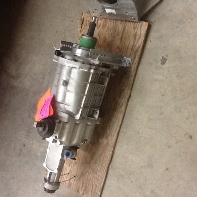
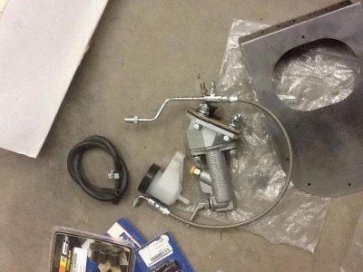
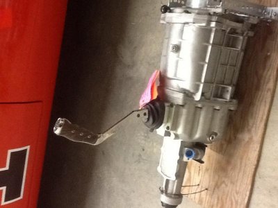
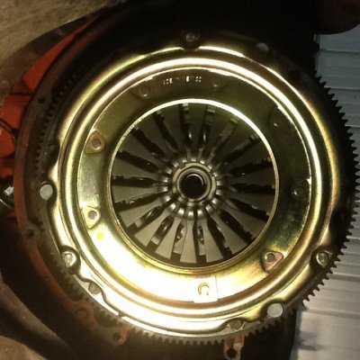
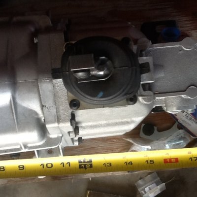
:grin:I got in from work yesterday to find all parts delivered. I want to thank Got6pak for fast shipping and packing it up so well. I unpacked it like a kid on Christmas morning. Took a bunch of pics to show you guys.:upside down:
- - - Updated - - -
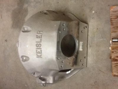
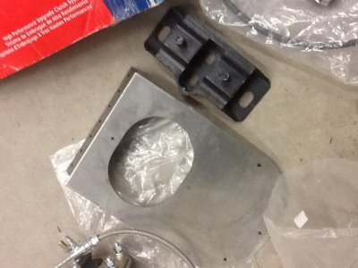
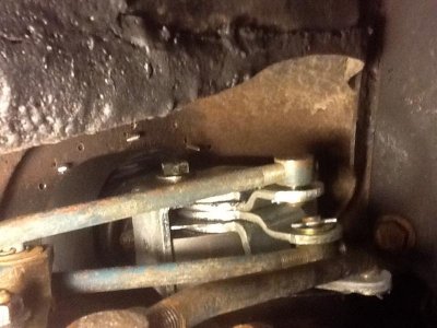
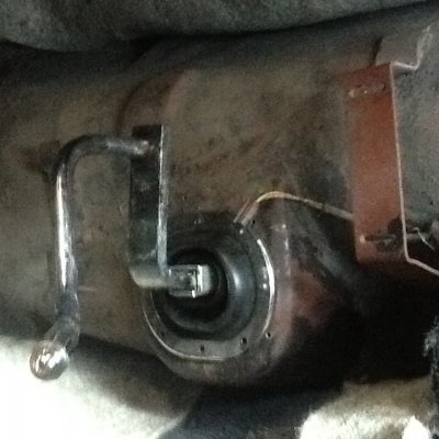
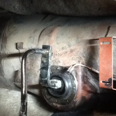
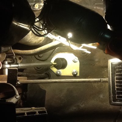
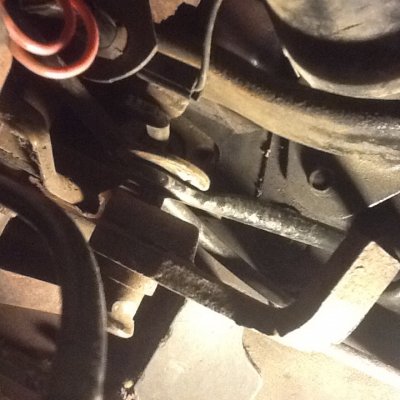
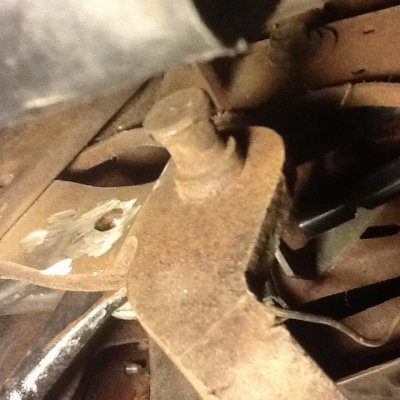
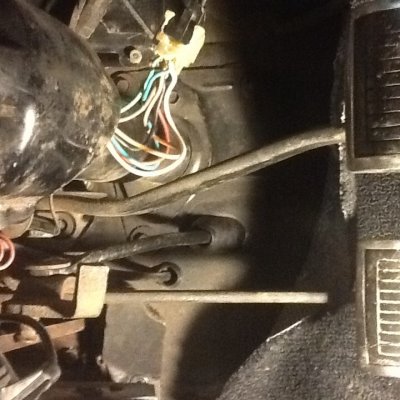
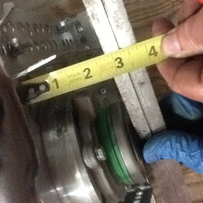
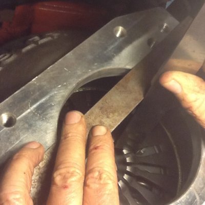
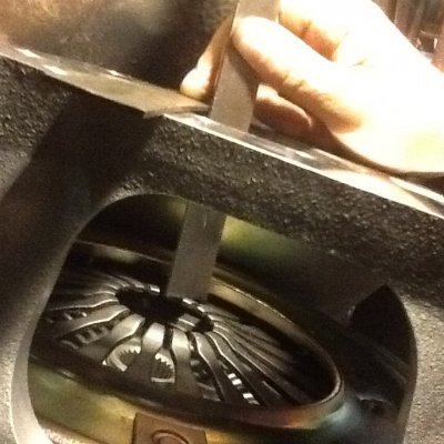
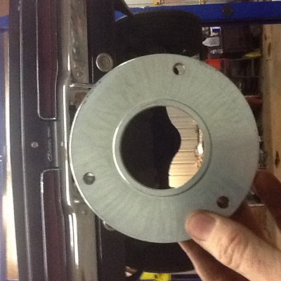
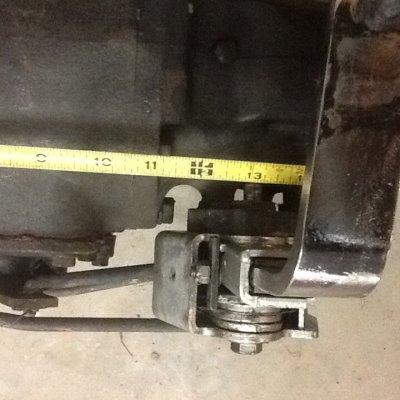
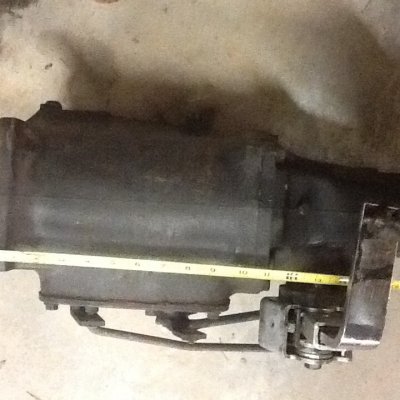
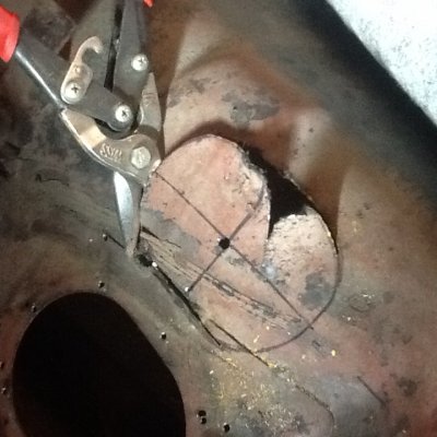
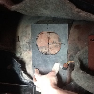
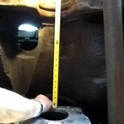
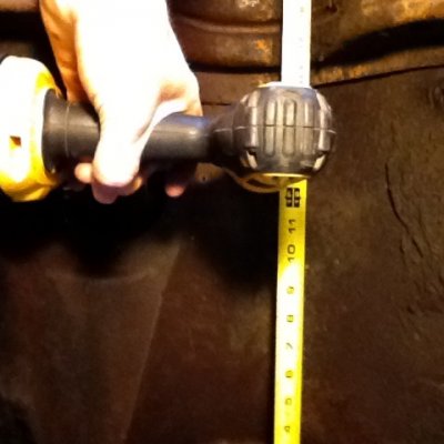
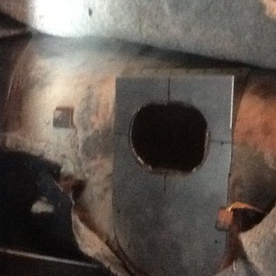
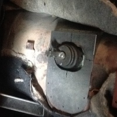
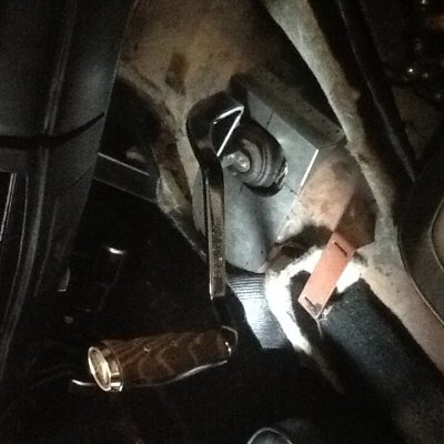
I was stoked about getting started. I could see by the parts,This could get a little intimidating for a backyard hobbiest like me. First thing that jumps out at me is this part. Overdrives is right about cutting the hole. This part is to fix center of tunnel.I took a pic of underside of hump so as you can see existing shifter penetrates the hump on side not center of tunnel.I guess I will have to cut atleast a hole in center of hump. When I get to that part, I will definitely share more info.
:hello2:8 inches of snow last night.No work today. I'll be in shop working on the trans. I'll be snapping pics to share with you guys.
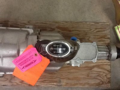
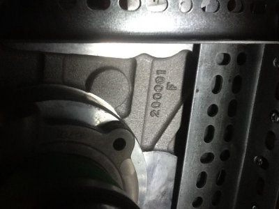
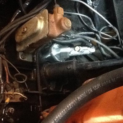
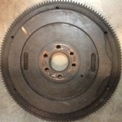
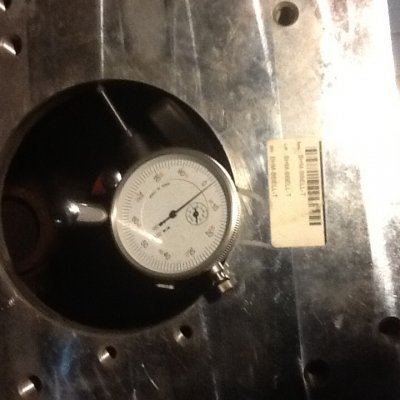
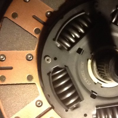
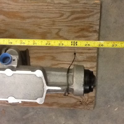
I did notice the serial num looks like could be first one.lol I don't know but check it out.
")