• When you click on links to various merchants on this site and make a purchase, this can result in this site earning a commission. Affiliate programs and affiliations include, but are not limited to, the eBay Partner Network.

My 1967 Belvedere Convertible Plans and Restoration (aka - Mad Scientist Build)

I really like the way the mounts are looking, they're not going anywhere! The mounts to the tranny look about as perfect as you could want and the frame mounts look like they could support a tractor tranny!!!!! One small suggestion, check your angle from a different location (if you haven't already). The best places to check it to be spot on accurate would be reading it off of the crankshaft pulley holding the angle finder facing up and down on the pulley, the bell housing face or against the end of the tranny output shaft if you have a flat surface there. Awesome fab work Kahn!
 
I've been checking there too . . . thanks for the heads up . . .

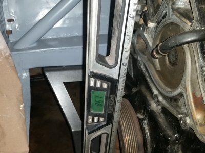
Thanks 747Mopar . . . here's the reading I get off the front of the crank pulley . . .

sm_thehemiisin46.jpg

That's giving me a reading of 3.3 degrees . . . is that "close enough", or do I need to raise the tail a little to get it to 3 degrees ? ? ?
 
Awesome work on the tranny mount Khan. Between you and Devin I'm watching intently so I can do the same to my Coronet, so thanks for the posts and Merry Christmas.
 
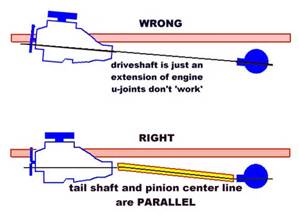
Nobody can say if 3.3 degrees is right or wrong, when you go lowering a car which I know you will everything changes but this picture illustrates what you want. Ideally you want the centerline of the tranny parallel with the pinion but not at a straight angle at either end. If you have no angle at either end and it's perfectly straight it won't vibrate but you'll eat up u joints because there has to be an angle to keep the needle bearings moving or they'll just pit the cups and not lubricate properly. My opinion would be to tack it up but wait until you have the rear installed at ride height before you fully weld it so you can adjust the angle if need be. I didn't know any of this when I installed my tranny but learned the hard way tracking down the vibration, had I known I would have mounted mine higher. Having said that my car is lowered 2" with a tranny angle of 3 degrees down with the pinion pointed up 3 degrees and the vibration is gone. Good luck Kahn.

th1FD16MUJ.jpg
 
Nobody can say if 3.3 degrees is right or wrong, when you go lowering a car which I know you will everything changes but this picture illustrates what you want. Ideally you want the centerline of the tranny parallel with the pinion but not at a straight angle at either end. If you have no angle at either end and it's perfectly straight it won't vibrate but you'll eat up u joints because there has to be an angle to keep the needle bearings moving or they'll just pit the cups and not lubricate properly. My opinion would be to tack it up but wait until you have the rear installed at ride height before you fully weld it so you can adjust the angle if need be. I didn't know any of this when I installed my tranny but learned the hard way tracking down the vibration, had I known I would have mounted mine higher. Having said that my car is lowered 2" with a tranny angle of 3 degrees down with the pinion pointed up 3 degrees and the vibration is gone. Good luck Kahn.

View attachment 299154

Back in the day when I was designing special machines and automatic assembly machines the rule of thumb was that regardless of what the output and input angle was they were to be parallel and the operating angle was not to exceed 3 to 12 degrees to maintain smooth operation and optimum life of the joint - so in other words if your engine centerline is 3 degrees and the pinion centerline is 3 degrees when you connect the dots the operating angle should be 6 to 15 degrees on the gauge.

Gary
 
the 3 degree rule is for engines running carbs most fuel injected engine are level in the engine bay as they due not require the engine tilt for fuel distibution as carbs do
 
I put 3 degrees back tilt on mine and absolutely no vibration whatsoever. I think the factory setup was 3 deg down and the pinion I believe sits 3 deg up. So that keeps the u-joints moving without getting anywhere near bind. He should be all set the way he did that.

BTW, looking very good Kahn. I am liking the way the mounts are coming together. It should make for a very stiff combo.

I was wondering how much clearance you will have around your engine for your headers/manifolds etc? Also what pipes did you elect to go with? I don't know what will fit with your combo but I have a set of 300C Manifolds in my garage that wouldn't work for me.
 
May try to remove to clean the area on your existing floorpan that your welding to. That may help with your weld quality. The car looks awesome! Looks like its in good, capable and motivated hands.
 
More progress . . . nice to have something to work on ! ! !

With the transmission mounts behind me ( kinda ) the Belvedere project has taken on a life of it's own . . . with plenty of thing for me to work on . . . and with the 4 day weekend ( ok, holiday ) I've been trying to keep working in the shop and making progress . . .

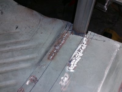
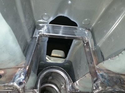
The original bolt in cross brace ( under the trans ) can not be used - I'm working on making a new one - but with the new transmission mounts, this under the transmission brace is really for additional side to side reinforcement, and for a catastrophic failure ( although I doubt it'll catch much if the trans fails that much ) . . . one of the through holes for the bolts had to get cut away so the trans would fit in the tunnel - so I drilled a new set of holes, and had to add bracing between the frame to prevent it from collapsing . . . here you can see where I've folded the floor away to weld in the bracing, and am tacking it back in place . . . ( think I may up this to 1/8" steel plating )

WOW - did the floors get really solid with these welded in place and not just spot welded ! !

sm_thehemiisin49.jpg

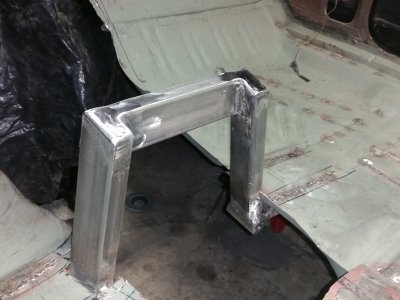
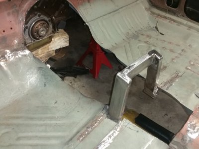
Got the over the top transmission brace re-designed and fabricated - it's now fully welded in place . . .

sm_thehemiisin48.jpg

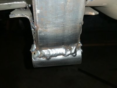
Here's a pic of one of my "better welds" . . . this was pretty high heat to really burn these bosses into place . . .

sm_thehemiisin47.jpg

And the view from under the tunnel - with the tunnel in place . . . the drive shaft loop may need to be moved a little up and back ( oh boy ! ! - more things to do ! ! )

sm_thehemiisin50.jpg

Next, get the trans back in place ( again ) and make sire that everything likes up and works ( that I didn't mess up something welding in the bosses ), and if all is well, then the engine and transmission come back out of the car, and the tunnel hump gets welded into place . . .

Then . . . uh, onto Bodywork ? ? ? ! ! ! ( uh boy ) . . .
 
With the transmission mounts behind me ( kinda ) the Belvedere project has taken on a life of it's own . . . with plenty of thing for me to work on . . . and with the 4 day weekend ( ok, holiday ) I've been trying to keep working in the shop and making progress . . .

The original bolt in cross brace ( under the trans ) can not be used - I'm working on making a new one - but with the new transmission mounts, this under the transmission brace is really for additional side to side reinforcement, and for a catastrophic failure ( although I doubt it'll catch much if the trans fails that much ) . . . one of the through holes for the bolts had to get cut away so the trans would fit in the tunnel - so I drilled a new set of holes, and had to add bracing between the frame to prevent it from collapsing . . . here you can see where I've folded the floor away to weld in the bracing, and am tacking it back in place . . . ( think I may up this to 1/8" steel plating )

WOW - did the floors get really solid with these welded in place and not just spot welded ! !

View attachment 299273

Got the over the top transmission brace re-designed and fabricated - it's now fully welded in place . . .

View attachment 299272

Here's a pic of one of my "better welds" . . . this was pretty high heat to really burn these bosses into place . . .

View attachment 299271

And the view from under the tunnel - with the tunnel in place . . . the drive shaft loop may need to be moved a little up and back ( oh boy ! ! - more things to do ! ! )

View attachment 299274

Next, get the trans back in place ( again ) and make sire that everything likes up and works ( that I didn't mess up something welding in the bosses ), and if all is well, then the engine and transmission come back out of the car, and the tunnel hump gets welded into place . . .

Then . . . uh, onto Bodywork ? ? ? ! ! ! ( uh boy ) . . .
Again ill say honestly.. Outstanding stuff! Im getting about as envious as can be seeing all this good, cool stuff going on, ill be back to it but i sure do like all this, You mention the body work and that's where im most comfortable myself, i enjoy every thing im doing but body work im looking forward to, i always tell Sue that some times (the days every thing is not going right) that i cant wait until im back to what i always used to do, painting is the final step and im wondering if ill remember how ROFL.....
 
Incredible work Kahn. I'll catch up on your thread and then when I jump into my stock driveline/stock suspension resto I can't complain about things not lining up.. lol. Hope you had a Merry Christmas.
 
More transmission cross member work - under the transmission . . .

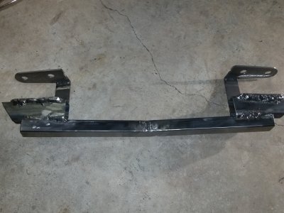
Now I've got to get the other part of the transmission cross member fabricated . . . the part that goes under the transmission and helps share the load of the original frame - before it got cut to allow this 6-speed to be fit up in the car ( with a whole lot of tunnel hump cutting . . . )

So my sights were set on getting this part of the cross member - a removable lower support - figured out . . . here's what I've come up with ( with some great coaching )

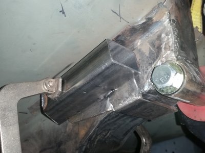
As much as I'd like the cross member to go straight across - it's going to have to move "aft" to allow it to clear the transmission . . . so I'm adding a little 1 1/2 inch spacer to the new parts that I made that will allow this part to be bolted into the car . . . and removed to allow the transmission to go in and out . . . ( that helps )

sm_thehemiisin51.jpg

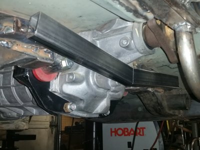
In addition, the new span has to dip down, just a little in the middle, to also clear the transmission . . . so I notched and bent the rectangular tubing . . .

sm_thehemiisin52.jpg

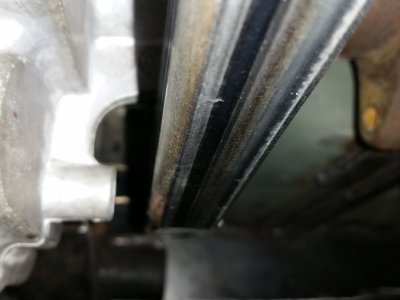
Here's the amount of clearance that I've got at the rear of the transmission - see why I needed the 1 1/2 spacers now ? ? ?

sm_thehemiisin53.jpg

More welding, and grinding, and capping off the tubing . . . ( M-A-G technology ) and this new removable lower frame support will be ready ! ! ! I think this will work out fine . . .
 
This is really cool to watch all this come together! Great work - I would not have the balls to do this because I would be afraid that I would get some goofy geometry wrong.

Well done!
 
Got the lower brace welded up . . . and it still slides back into place ! !

Got the rest of the welding done on the lower bracket . . . and the thing still slides back up into place where it's supposed to go ! ! ( that's good )

Here's the lower bracket - you can see the parts that wrap around the frame and where the bolts pass through - the nuts are welded in place.

sm_thehemiisin54.jpg

Still need to cut and weld caps on all the open ends of the rectangular tubing . . . and ( of course ) do some more grinding on the welds to clean them up a bit more.


GUESS WHAT . . .

The engine and transmission are coming out of the car so that I can work on the tunnel hump and get it welded in place ! ! ! !

- - - Updated - - -

Larry you are nailing this!!!! Well done man that is some fine work!

Thanks for the kind words and encouragement there Goon ! ! ! ( SMILE )

- - - Updated - - -

This is really cool to watch all this come together! Great work - I would not have the balls to do this because I would be afraid that I would get some goofy geometry wrong.

Well done!

Thanks Hawk . . . it's pretty fun watching the thing "come together" on this side too . . . and I'm having a blast ( now if I only knew what in the heck I was doing ! ! )
 
Happy New Year to everyone at FBBO ! !

Happy New Year to everyone at FBBO - Hope that 2016 is healthy, safe, and successful in everything that do ! !


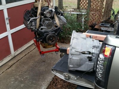
It's a sad day in the "Mad Scientist Build" shop as the Hemi engine had to be removed from the car . . . ( sigh )

But . . . to keep with the recent momentum that I have had pushing me on the car, the engine coming out is a GREAT THING, and that means that I'm now ready to get the transmission tunnel hump finished and welded into place in the car ! !

Dropped the transmission out of the car last night - I was kinda getting use to seeing it filling up the hole . . .

sm_thehemiisin55.jpg

And I checked off the "Wrestling with a Hemi" from my bucket list . . . as I wrestled with this bad boy so that it can go back in the garage for safe keeping . . . for a little while

sm_thehemiisin56.jpg

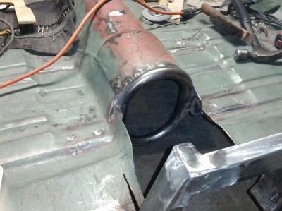
Now to work on the tunnel hump . . . Oh, the drive shaft loop was removed from the car - as it caused issues with installing the transmission ( about 1/2" ) . . . so it's getting moved back so it son't be in the way in the future . . . a little pain, but so much easier to do it now then try and do it later . . . so out it came . . .


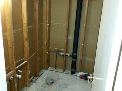
And if that's not enough . . . got a bathroom destruction project going on at the same time . . .

sm_remodellingbathroom01.jpg

The "pergo flooring" ( which I can't stand - why put it in a bathroom ? ) was all warped, as water got under it, then under the pergo was Vinyl Flooring ( glued to the floor ) - but it was not the floor, it was the 12 x 12 tiles that were actiually glued to the floor . . .

Not plywood either . . . it's particle board ( yuck ! ) . . . so all the particle board has to be removed, and replaced with 3/4" plywood - then concrete backer board to support the ceramic tiles that will be installed . . . at least it keeps me out of trouble ( and the carport is all done ) . . .
 
Last edited:
Looking good Kahn, so we're going to see that tunnel in there tonight right???? I'll be interested to see what you do for a console haha, looks like you could just carpet that tunnel, install a cup holder and call it done! That should set you up for a full length center console and 2 buckets in the back too?
 
Tunnel hump installed "tonight" ? ? ? ?

C'mon 747 ! ! This is me . . . I'm not quite as fast are you are ! ! Maybe I need to check into that Cracken ! ! !

On my progress . . .

Hemi is pulled out and tucked away in the garage ( with my red-neck cherry picker pick up truck )
Transmission is out of the car and keeping the Hemi company
The Magnum Force K-member has been removed and is in the house ( LMAO - not in the garage ? ? )
Got the car back in the shop and all leveled up
And . . . got started on the drive shaft loop ( cleaned up after removal ) and floor cut back for more room . . .

And . . . it is now back in the car where it belongs !

sm_thehemiisin57.jpg

Now to work on that tunnel hump . . . ( maybe . . . have it moving along nicely by the end of the weekend ? ? ) Will that work ? ?
 
Really glad to see you're rolling along with this thing now. I figure the magnum force Kevin member would make a good coffee table!!
 
wow khan, alot of work right there. looking real good. if there is a will there is a way. like a little trans mount was gonna get in your way. lmao....nice job!!!
 
Auto Transport Service
Back
Top