• When you click on links to various merchants on this site and make a purchase, this can result in this site earning a commission. Affiliate programs and affiliations include, but are not limited to, the eBay Partner Network.

Where to adjust Camber, Caster and toe-in

Stagepirat

Well-Known Member
Local time
9:01 AM
Joined
Oct 5, 2016
Messages
48
Reaction score
9
Location
Munich, Germany
Hello dear members.
I need my front end to be aligned. The car is a 1973 Dodge Charger.
The problem is, that here in germany there are a lot of experienced garages, but not experienced on old mopars.
So maybe some of you guys could post me pictures (best would be with "arrows" pointing to the concerning screws) where to adjust the camber, caster and toe-in.
I was in three different garages and all three of them wanted to start working on another part of the front to align the same issue.... They never had a car like that to work on it before.
Of course I checked the manual before, but could´t find any pictures or drawings. And only by naming the parts I still risk to misunderstand something.
By the way: is there any special tool required?
 
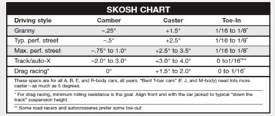
These are the specs I will try to achieve:

Bildschirmfoto 2018-07-18 um 09.43.14.png
 
Hello dear members.
I need my front end to be aligned. The car is a 1973 Dodge Charger.
The problem is, that here in germany there are a lot of experienced garages, but not experienced on old mopars.
So maybe some of you guys could post me pictures (best would be with "arrows" pointing to the concerning screws) where to adjust the camber, caster and toe-in.
I was in three different garages and all three of them wanted to start working on another part of the front to align the same issue.... They never had a car like that to work on it before.
Of course I checked the manual before, but could´t find any pictures or drawings. And only by naming the parts I still risk to misunderstand something.
By the way: is there any special tool required?
In order to get the best performance from the front steering geometry you are best to go to a shop with an alignment machine, preferably one that's up to date. Doing it yourself is "iffy" at best. Any shop that's armed with the required specs should be able to perform this and give you a printed sheet of the final results. As for not knowing where to make these adjustments it's not really rocket science. Understanding toe, caster and camber should be common knowledge to any alignment shop and the places to perform adjustments can be easily realized by looking at the type of suspension. I'm sure if they are a good shop, they can figure it out, if not, you're in the wrong place. Use this guide for your own information and maybe theirs too.

https://www.allpar.com/history/mopar/front-end-alignment.html
 
Caster and camber are both adjusted with the upper control arm cam eccentric bolts.

Toe in/out is adjusted last, using the tie rod adjusting sleeves on both sides.

FSM has all the diagrams. This is for '69 & '70 models, your '73 should be virtually identical.

Wheel Alignment pg1.jpg


Wheel Alignment pg2.jpg


Wheel Alignment pg3.jpg
 
Yes the 73 and up models require a special tool to adjust caster and camber. A good 73-78 FSM will list the required tools. Its not rocket science.
The 66 - 72 FSM will be of little value if the German mechanics are looking for the points of adjustment.
If given the proper manual they will figure it out.
 
For everyones info that doesn't know. Chrysler corp discontinued using bolt with cam adjusters with the 1972 model year.
At your next cruise, car show or gathering take a look at someones 73 or newer mopar. Take a good look, get educated.
 
For everyones info that doesn't know. Chrysler corp discontinued using bolt with cam adjusters with the 1972 model year.
At your next cruise, car show or gathering take a look at someones 73 or newer mopar. Take a good look, get educated.

Thanks for the info, no I didn't know that they had changed in the mid '70's, obviously. Never did like the look of '73 and later with the "rubber baby buggie bumpers", and along with the "weenie" smog engines from that era they were like kids toys compared to the real muscle cars I grew up with, so never did "take a good look" and didn't get all "edumacated" like you. So sorry, my bad!

But, my point is still valid, it's in the FSM.
Correct if looking at the correct FSM.

Were our old mussel cars really all that great considering in 73 hp was taken different than in 72.
No more throwing a striped engine on a dino. 73 and up were rated with full operating accessories
 
First of all: Thank you for your help.
Unfortunately I couldn´t find anything about the "73 and up models require a special tool to adjust caster and camber. A good 73-78 FSM will list the required tools" -Tool...
In fact, I don´t even know what to look for... Maybe someone here has a picture of a similar looking tool.
I suppose FSM means something like "Front Suspension Manual"?

And to say something about the "rubber baby buggie bumpers" - They were the first thing I got rid off.. Prefered the Hidden-Headlight looks. Then swaped the 1974 318ci to a 440HP form 1969, put in a A833 and a 8 3/4 Sure Grip. Within the financial limitations and the lack of a big choice in cars an replacement part I just try to make my car the car I always wanted... The only numbers that still match are the front and rear license plates....
 
Thanks for all your help. I studied all the Manuals, but on my 73/74 Charger it looks slightly different and in the Manual for my Build-Year there are not pictures.
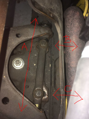
So just to be sure. With the screws A, B and C on the picture I can aligne what exactly?
Sorry for so many maybe stupid questions and thanks in advance....

Spur einstellen Charger.JPG
 
A are shaft bearing for the upper control arm. Nothing needs to be done there unless there is other movement other than rotational.
B & C will be used to set caster and camber.
Set caster first and camber last.
 
Thank you.
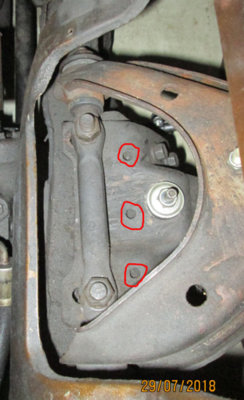
I have last question. What are these three holes for? Is there a tool or something that I can jam in there? Because when I try to caster and camber, it takes me a lot of force an I have to use a crowbar to move the alignment. Shouldn´t it go a little bit easier?

Charger achse.jpg
 
The holes are for the tool. I've done plenty of them. You can do it without the tool. The tool hooks over the upper control arm shaft so you can pull on the shaft. This will pull the arm outward. Tips and tricks; NEVER loosen the bolts with the car setting on the tires. Jack the front end anywhere but the outer control arms. This will let the suspension drop taking the load off from the upper arms. Now crack the bolt loose 1/4-1/2 turn on the end (front or rear) that you do NOT want to adjust. Loosen the opposite bolt and move the arm. When jacked up correctly, it moves easily with a pry bar. Now tighten it all up. Lower and take a caster/camber reading. If it's not correct, repeat the procedure. If you loosen the the bolts with the car setting on the wheels, the control will pop inward to the end of its travel. If you loosen both bolts the arm will slide around and you will loose any idea of where your current specs were. These can be difficult to master. However someone that knows them, it's piece of cake. I've reset many where somebody "lost it" on the adjustment.
Doug
 
And dont forget to settle the front end before taking readings. It can be done by bounce or roll method.
 
Thanks. That already helps me a lot. What I still could´t find is a picture that tool or even better a way to get it? Is there a store where I can purchase it? Ebay? Or is it possible to build it myself? If yes I would need to know how it looks. Or maybe someone here in the forum has one to sell....
 
I have the tools. When it's jacked up they are unnecesary. More trouble than they're worth. It's a hook that goes over the shaft. This is connected to a long handle with a pivot pin. At the bottom of the handle there is a pin. The pin. goes into the hole in the frame behind the shaft. When it's installed the pin in the hole gives you leverage to pull/push on the control arm shaft.
Doug
 
Good thing someone has them. Should not be to difficult to make if memory hasn't failed me.
 
Auto Transport Service
Back
Top