• When you click on links to various merchants on this site and make a purchase, this can result in this site earning a commission. Affiliate programs and affiliations include, but are not limited to, the eBay Partner Network.

Dissection and Study of 1971 Philips AM/FM Multiplex Stereo

MoparGuy68

Well-Known Member
Local time
9:19 PM
Joined
Mar 31, 2019
Messages
780
Reaction score
550
Location
Phoenix, AZ
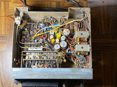
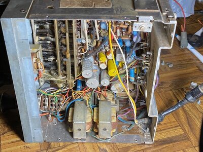
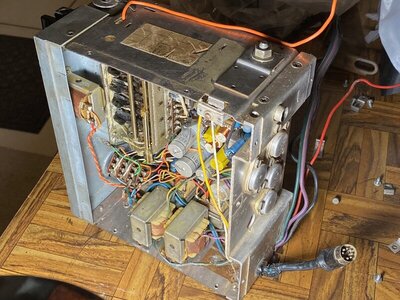
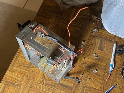
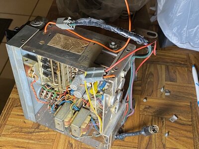
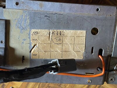
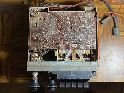
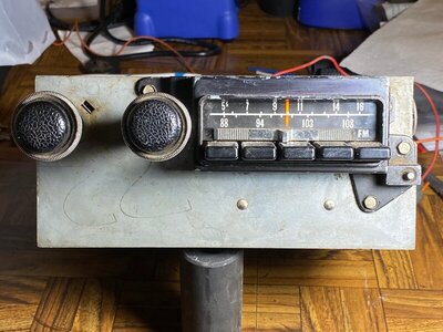
My 71 Charger came with the R36 radio option. Tonight, I opened up the AM/FM Multiplex Stereo to see what it looks like inside, while it is out of the car.

So far, after reading my FSM, I have not been able to confirm whether the red power wire takes the full 12 volts from the battery, or not. I see what looks like five transformers inside the radio chassis, so perhaps it does take 12 volts as input.

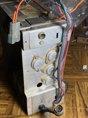
I'd like to bench test this radio while it is out of the car because I don't know whether it works or not.. Probably take my car's battery, connect the red wire to the positive battery terminal and connect a wire from the negative battery terminal to the radio's chassis. Also trying to figure out how the blue, green and black speaker wires should be connected to two speakers. I don't know what speaker Ohm impedance should be used with this radio. I have a pair of 8 Ohm speakers that I could bench test with.

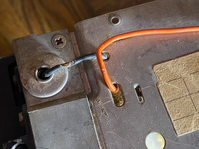
When it was in the car, only red power wire was connected to the harness. No other wires were connected. There are two speakers in the car, one in the middle of the dash, and one under the driver side of the package tray. Someone cut the orange wire from its harness connector. I cannot see exactly where it goes, but it must connect to a bulb to illuminate the dial indicator when the car lights are on. I cannot see this bulb.

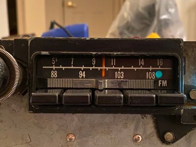
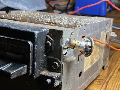
I do see a bulb on the right side of the chassis, that only appears to illuminate the green circle that indicates successful tuning of an FM Stereo signal.

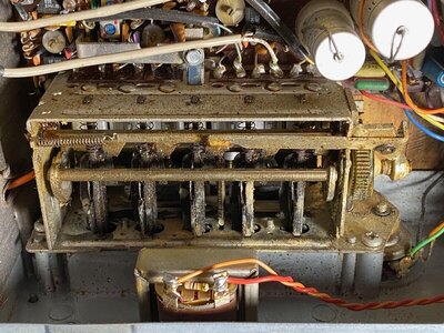
The preset push buttons are supposed to work as follows. Pull a button as far outward as it will go, tune to the desired station with the dial, then push the button as far in as it will go. After doing this the preset station should be set for that button. From years ago I remember this type of preset action, from the AM/FM Stereo radio in my father's 1971 Buick LeSabre. I have no idea how this actually works, to "remember" the tuned station and recall it when the button is pressed.
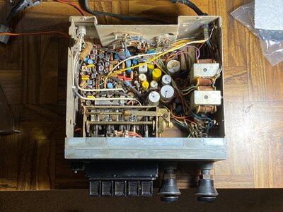
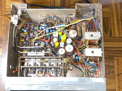
IMG_4781.jpg IMG_4784.jpg IMG_4785.jpg IMG_4786.jpg IMG_4787.jpg IMG_4788.jpg IMG_4789.jpg IMG_4790.jpg IMG_4791.jpg IMG_4793.jpg
 
I was an electronics tech in a past life. They say education is what you have left after you forgot what you learned in school and that's what I have left. Anyway for some reason this fascinated me so I'll give my .02c which is worth every penny you paid.
The +12v is no doubt correct since I never heard of a DC radio in a 12v car system that used any other voltage. Your speaker impedance should be safe at 8 ohms. With that many transformers it is logical that two of them are audio couplers which are pretty forgiving of impedance matching.
The speaker wires look like green, violet black to me. Its a good bet that black is ground shared by both speakers and the green and violet are front and rear. Once again, with a transformer coupled output it is likely forgiving of wiring mistakes even if you wired front to back on one speaker. The mechanical preset selector I know nothing about except it looks old, dry and brittle. I would blow it out gently with air to get out the dust and then spray with electrical contact cleaner (you can spray that stuff anywhere and it flashes off clean, no residue) and put maybe a drop of light oil, (do they still make 3 in One?) on the moving parts to loosen it up? I wouldn't use any spray lube that got in the electronics.
My question is about the 7 pin DIN plug. Was there an optional 8 track or graphic equalizer available in 71? That's the only explanation I can think of.
Good luck with it. IMO it would be way cool to have a working original radio in the car!
Oh, you probably already know, but a coat hanger stuck in the antenna socket will work for bench testing if you don't have one handy.
Have fun!
Bernie
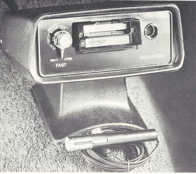
I think the 7 pin DIN plug went to the optional console mounted cassette player/recorder that was available in the 71 Charger/Road Runner.
 
I know back in 1971 at least as far as GM goes they used 10 ohm speakers in everything. I would assume Chrysler & Ford did the same but not positive on that. You might want to look for a radio manual on ebay that could sort out alot of your questions.

Preset on GM vehicles you would get the dial to your favorite station pull out on the closest pushbutton and push it back in and you are all set. You are correct in powering up for test red - 12v, ground to chassis.

God luck
 
IMO....
The larger transformers mounted on the inside of the enclosure are likely the output transistor's impedance matching component, which matches the transistor network to the speakers input impedance, usually 8-16 ohms. The smaller of the tranformers, under the larger transformers, are likely interstage driver transformers that match the audio amplifier network to the driver transistors that feed the output transistors. The little square devices with the slotted adjustment screws on top are the AM and FM intermediate frequency amplifier coupling transformers. The AM intermediate frequencies are usually 455 KHz snd the FM intermediate frequency frequencies are 10.4 MHz, prior to the AM detector and FM ratio detector circuits. The detector circuits, sttip off the carrier wave leaving just the audio portion of the signal. There is also a FM multiplex oscillator and detector circuit that splits the multiplex signal into the left - right side or front - back speaker arrangement.
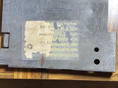
If you know the radio's model number or chassis number, Howard W. Sams publishing company, look on internet, you can find complete servicing instructions including the main schematic diagrams and a basic how it works explanation and all adjustment procedures including IF alignment procedures.
BOB RENTON
 
somebody may interest this... not perfectly scanned but is what I found... somewhere

TUNER SECTION
tuner section1.JPG
tuner section2.JPG


AMP SECTION
amp section.JPG
 
Last edited:
well... the image resizing of the board is not helpfull

BTW. Red is positive, ground is chassis. Orange is face light, black is speakers common ground, green is left chanel, violet is right channel.

AND... you can become the DIN 7 connector in a LINE IN setup... ( I'm searching the thread about what I made on mine at dodgecharger.com )

TO BE ABLE TO BENCH TEST THE RADIO WITHOUT A CASSETTE PLAYER IS A MUST THE JUMPER PLUG CONECTED TO THE PIGTAIL TO LINK THE TUNER LINE OUT TO AMP SECTION LINE IN INTO THE SAME RADIO

The pigtail gets the out signal to the cassette player. Cassette player gets the function selector ( Radio or Cassette ) and the selected signal returns to radio into the amp section.

If you don't have the jumper plug attached, the Amp section of the Radio won't ever get the Tuner signal.

If the jumper plug is missed, it can be made with a regular DIN 7 ( or even 8 ) female conector, solding the jumpers into the female plug
 
Last edited:
This is how it looks the Cassette player pigtail with the jumper plug/cap installed when the car was not equipped with the cassette player but still getting the multiplexer Radio ( for whatever reason )

71%20radio%20bk%20w%20cassette.jpg
 
Nacho, thank you!!

Question about the lighter socket. Is it just wired in just to provide another socket to power a phone or audio player?

This may also explain why the one I have 'didn't work', because I don't have a plug in mine, just an open 7-pin.
 
Yes! The DIN plug provides also the power to the Cassette player, so I thought on use that source to feed whichever audio player power adaptor and keep the ashtray still closed on dash... or still be able to use the lighter if needed without disconnect the power source for the player ( althought I don't smoke )
 
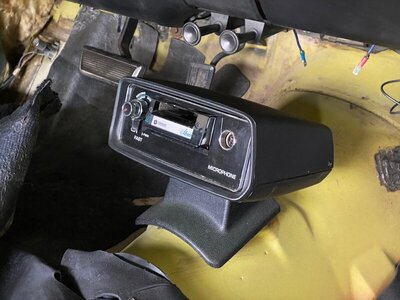
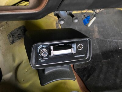
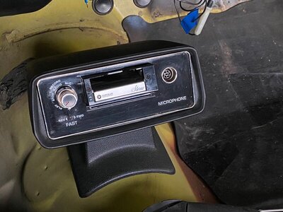
R36 option = AM/FM Multiplex Stereo with Stereo Cassette Player/Recorder. So yes, my car came from the LA Plant with this option and I have both units. Both units are untested and I don't yet know if either or both of them work. The DIN cable that connects them is in bad shape, so I'll probably need to source a replacement for it.

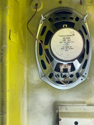
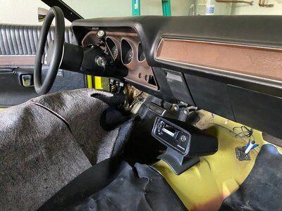
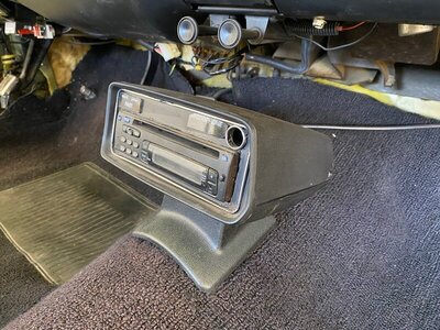
When I got the car it had a modern (probably late 1990's vintage) Radio Shack AM/FM Stereo CD player mounted in the Cassette housing on the floor. This was done using cardboard and a hacked face plate from another Cassette Player unit. Factory Multiplex unit was in the dash, with only the red power line connected to it. I checked the front and rear speakers, they are both Radio Shack 8 Ohm. Speakers were connected to the Radio Shack Stereo, which drew power from the ACC terminal on the fuse box. I threw the Radio Shack Stereo in the trash, never tried to operate it. It looked like a piece of junk and I didn't want it in the Cassette housing..

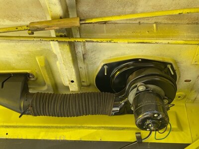
Rear speaker is under the package tray on driver side. The rare H31 Rear Window Defogger is under the package tray on the passenger side and middle.

Took some photos of a test mount of the Cassette Player/Recorder in the housing attached to the floor pan hump. Included one of the Radio Shack Stereo when it was mounted in the Cassette housing.

Some radio option trivia for 1971:
R11 Music Master AM radio $66
R26 AM radio with Stereo Cassette Player/Recorder $219
R35 AM/FM Multiplex Stereo $213
R36 AM/FM Multiplex Stereo with Stereo Cassette Player/Recorder $366 (more expensive than the 440 SixPack engine option, most expensive option on my car)

H31 Rear Window Defogger $31.45 (Rarest option on my car, with the R36 as second rarest)

IMG_4810.jpg IMG_4811.jpg IMG_4812.jpg IMG_4846.jpg IMG_4853.jpg IMG_4854.jpg IMG_4855.jpg IMG_4856.jpg IMG_3710.jpg
 
Last edited:
I actually would say the sunroof is the rarest of all options and Cassette player is the 2nd rarest being the floor mounted one even rarest than console mounted. I wouldn't say the rear deffogger is rarest than the Cassette player. Have seen it in many cars. I think in fact Power windows are rarest than the deffogger.

I don't have the facts, sure, but just by 18 years of observation on the web.
 
I actually would say the sunroof is the rarest of all options and Cassette player is the 2nd rarest being the floor mounted one even rarest than console mounted. I wouldn't say the rear deffogger is rarest than the Cassette player. Have seen it in many cars. I think in fact Power windows are rarest than the deffogger.

I don't have the facts, sure, but just by 18 years of observation on the web.
When I say rarest and second rarest, I meant of all options ordered on my car. I came to this conclusion by checking the Super Bee Registry. Of all 1971 Super Bees in the registry that have option codes, only 2 cars have the H31 option. Only 3 cars have the R36 option. Include my car then that makes 3 cars for H31 and 4 cars for R36. How many are GY3 with H31 and R36? Maybe just mine..
 
Mmm ok, dunno on the specific breakdown about Superbees and on registry. I just can talk on a somehow "average " between all B bodies I have seen on web. :D
 
My question is about the 7 pin DIN plug. Was there an optional 8 track or graphic equalizer available in 71? That's the only explanation I can think of.
Good luck with it.
Bernie

Bernie, the 7 pin goes to a cassette player, not 8 track and mounted on the tranny hump

FB_IMG_1588249694714.jpg

Looks like other members beat me to it
 
Last edited:
Moparguy-Do you have a console or not in your car? I know they made 2 different bases for the cassette, depending on with or without console and I seem to get them mixed up. Also, I think there were 136(?) with R36 option
 
Auto Transport Service
Back
Top