• When you click on links to various merchants on this site and make a purchase, this can result in this site earning a commission. Affiliate programs and affiliations include, but are not limited to, the eBay Partner Network.

Voltage drop -- how is this possible?

JG1966

Well-Known Member
Local time
10:57 AM
Joined
Mar 16, 2015
Messages
417
Reaction score
164
Location
Pittsburgh
So, I've been chasing my 14.95 overcharging battery on my 72 RR. Here are my voltage drops testing from battery positive
Red wire connector at Molex (engine side, closer to bulkhead) .16
Blue wire at Molex (engine side) .21
Ignition switch (probing blue and red wires on switch side of Molex) .12
Blue igniton wire at bulkhead connector .71
Blue ignition wire at ballast .62
Blue wire connector at alternator .74
HOW can my voltage drop be more at the blue bulkhead connector than at the blue wire at the ballast? Ballast is "downstream," I thought. Shouldn't it always be the same or more?
Thanks
 
Last edited:
History on electrical system. All factory ? Upgrades ? Ignition ? Charging system ? Add on's ? More info, better diagnosis.
Maybe pictures of your system connections...
 
History on electrical system. All factory ? Upgrades ? Ignition ? Charging system ? Add on's ? More info, better diagnosis.
Maybe pictures of your system connections...
Thanks Leo. Everything is pretty much stock except an aftermarket 95 amp Powermaster alternator. I also did the MAD ammeter bypass and installed a headlight relay. I was at 15.5 volts before, and after cleaning connections and redoing some wiring crimps, etc.., I've gotten it down to 14.95. For a 72, the bulkhead and wires are in really nice shape (the car has been garage kept and rarely driven since the late 80s).
 
Thanks Leo. Everything is pretty much stock except an aftermarket 95 amp Powermaster alternator. I also did the MAD ammeter bypass and installed a headlight relay. I was at 15.5 volts before, and after cleaning connections and redoing some wiring crimps, etc.., I've gotten it down to 14.95. For a 72, the bulkhead and wires are in really nice shape (the car has been garage kept and rarely driven since the late 80s).

I also agree....more info is needed, along with pix and possibly a hand drawn schematic diagram. Please explain the details of the MAD amp meter bypass and how did you source the headlight relay modifications. And WHY did you change to a 95 amp Powermaster alternator? Was it the single wire type or just the higher capacity unit that resembles the stock Mopar square back unit with higher capacity stator windings and diodes? If it is the one wire Powermaster unit, it is possible that its internal regulator is allowing the higher system voltage.
Consider, with the engine running, DISCONNECT one of the 2 alternator field wires, if possible, assuming the Powermaster unit is a higher capacity unit, rather than the one wire type. This will stop the alternator's charging, then recheck your voltage drop points to see if there is any voltage feed-back, coming from the alternator and its wiring. What are you using to check voltage with.....a Fluke instrument or something from Harbor freight or ???? How accurate is it? Just thinking out loud......
BOB RENTON
 
"Pretty much, except...." lots of gray there. Exact answer needs exact info.
I guess I didn't need "pretty much." It's all stock, from what I know. For example, I don't know for sure that the ignition switch has never been replaced. I got the car in 1988. It might have had some changes from 1972-88. But the alternator, the MAD ammeter bypass and the headlight relays are definitely not stock.
 
Last edited:
I also agree....more info is needed, along with pix and possibly a hand drawn schematic diagram. Please explain the details of the MAD amp meter bypass and how did you source the headlight relay modifications. And WHY did you change to a 95 amp Powermaster alternator? Was it the single wire type or just the higher capacity unit that resembles the stock Mopar square back unit with higher capacity stator windings and diodes? If it is the one wire Powermaster unit, it is possible that its internal regulator is allowing the higher system voltage.
Consider, with the engine running, DISCONNECT one of the 2 alternator field wires, if possible, assuming the Powermaster unit is a higher capacity unit, rather than the one wire type. This will stop the alternator's charging, then recheck your voltage drop points to see if there is any voltage feed-back, coming from the alternator and its wiring. What are you using to check voltage with.....a Fluke instrument or something from Harbor freight or ???? How accurate is it? Just thinking out loud......
BOB RENTON
Thanks Bob. The MAD ammeter bypass was done as described on their website. I got the headlight relay and wiring from FBBO member Crackedback, who sells them. I got the Powermaster 95 amp alternator because my stock alternator died. It's a two-wire squareback style. My multimeter isn't a Harbor Freight. It's a good, accurate new multimeter. I haven't checked for voltage drop with one of the alternator field wires disconnected. I've made sure the battery wasn't charging with those disconnected but I haven't checked voltage drop. I'll give that a try and see what I get
 
Thanks Bob. The MAD ammeter bypass was done as described on their website. I got the headlight relay and wiring from FBBO member Crackedback, who sells them. I got the Powermaster 95 amp alternator because my stock alternator died. It's a two-wire squareback style. My multimeter isn't a Harbor Freight. It's a good, accurate new multimeter. I haven't checked for voltage drop with one of the alternator field wires disconnected. I've made sure the battery wasn't charging with those disconnected but I haven't checked voltage drop. I'll give that a try and see what I get

Again, thinking out loud.....
Since you are using a "square back alternator" with a 2 wire field supply, the blue wire at the alternator is connected to the switched power of the ignition circuit, as the FSM calls "the #1 splice", it also furnishes the voltage regulator the system's reference voltage (battery) to control the alternator's field voltage and current to provide the correct charging parameter (14.5 volts [+/-]). IF your system voltage is high, perhaps your existing voltage regulator is defective OR the the reference voltage connection (#1 splice connection) is a high resistance connection OR the voltage regulator case to ground is defective (high resistance connection to ground....it should be zero) or some combination of all these possibilities. Just my opinion of course...
BOB RENTON
Thanks Bob. I have tested and swapped voltage regulators. It's good. There is no voltage drop at all on the voltage regulator case. It's grounded really good. As far as "the #1 splice," that could be an issue. But the vast bulk of my voltage drop is happening "before" there. That's what has me confused. My voltage drop is less at the voltage regulator -- which comes "after" the #1 splice -- than it is at the blue ignition wire connection at the bulkhead. That doesn't compute.
 
Hey would you explain how the
“voltage drop test” was done.
Drawing and/or pic helpful.
Why do you think 14.95 charging voltage is not correct?
 
Wasn’t there another thread on this subject not too long ago? You won’t get to a “0” voltage drop between the ignition 1 at the regulator and the battery post with 50-year old stock wiring and connectors. IIRC, the total factory spec tolerance is around .5 volts, sounds like you are close to that. By-pass the Ignition 1 Packard terminals in the bulkhead and/or the Molex terminals at the ignition switch. Or as mentioned in the other thread, replace them with better quality, lower resistance connections. As mentioned previously, if you still don’t like your charging voltage after reducing the voltage drop on the regulator reference circuit as low as possible, use an adjustable regulator and adjust accordingly.
 
Last edited:
This....

6004178-dmm-whatis-ohm-top-1500x1000.jpg
 
Mike,
I'm well aware of Ohm's Law and Kirchoffs voltage and current laws as well ....as I hold a B.S. in Electrical Engineering and hold a Professional Electrical Engineer credential as well. I was trying to explain the operation of the system to those people that would benefit from a little simplification......but every nugget of information helps with the understanding.
BOB RENTON
 
At last...an answer without all the highfaluting technical details. :thumbsup:

Voltage drop is simply down to how and where you measure the voltage at two points.

You are measuring the amount of drop in a circuit across two points of resistance.

BTW, I am not a Professor of Electrical....I just get **** done. Been doing it long enough. :D

upload_2021-3-23_8-10-11.png

All steel construction. :p
 
As mentioned previously, if you still don’t like your charging voltage after reducing the voltage drop on the regulator reference circuit as low as possible, use an adjustable regulator and adjust accordingly.[/QUOTE] This exactly what I did with my car. I'll admit I was lazy. Mine was at that border line of 14.5 volts, maybe a titch higher. Battery was sweating a little and made me concerned. I bought an adjustable voltage regulator from eBay. Set it up to get no more than 14.1 volts max at 1500 rpm, which netted me 13.9 volts idling in gear. It was this one: https://www.ebay.com/itm/1970-87-Ex...Plymouth-HD-/274319793437?hash=item3fdebbdd1d
 
Last edited:
This is why I always go with internally regulated units and lower amperage, such as the Denso 65-amp setups from AR Engineering. You really don't need a large amperage alternator on these cars, especially with mechanical fuel pumps and clutch fans. Solves a lot of these small, but time consuming issues that seem to occur.
 
Mike,
I'm well aware of Ohm's Law and Kirchoffs voltage and current laws as well ....as I hold a B.S. in Electrical Engineering and hold a Professional Electrical Engineer credential as well. I was trying to explain the operation of the system to those people that would benefit from a little simplification......but every nugget of information helps with the understanding.
BOB RENTON
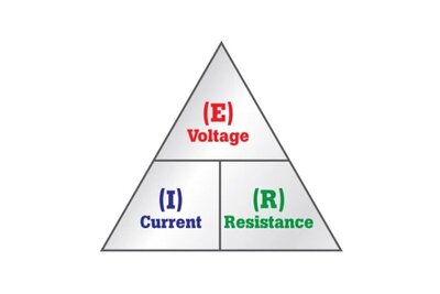
It may be overly simplifying the OPs issue, but in order for anyone to understand voltage drop they should understand the why. I & E being proportianate and inversely to R
9 times out of 10 in a DC circuit there is a resistance in the circuit that has changed causing the issues. Either corrosion, or contact tension usually being the culprit which all subsequently lead to the coup de grace' of any failing electrical system - heat.
 
At last...an answer without all the highfaluting technical details. :thumbsup:

Voltage drop is simply down to how and where you measure the voltage at two points.

You are measuring the amount of drop in a circuit across two points of resistance.

BTW, I am not a Professor of Electrical....I just get **** done. Been doing it long enough. :D

View attachment 1087339
All steel construction. :p

Not exactly sure what you are trying to say or the point you're trying to make. "I get sh** done" means what? Everyone, or just about everyone, knows that when sh** happens.....then you step in it. Hopefully, this is not the case.
BOB RENTON
 

The video above may help.
Try this, unplug the two wire terminal at the voltage regulator and let it hang. Run a bypass wire from the battery positive post directly to the terminal on the voltage regulator that the blue wire goes to, jump the green wire in the regulator wiring plug to the post it is supposed to go to. Doing this will bypass all the wiring and connections between the battery and the voltage regulator. start the engine, if your charging voltage comes down to normal, 13.8 to 14.2 with a fully charged battery, you have a bunch of high resistance connections in the wiring. Such as ignition switch run contacts, bulkhead connector terminals, fuse block terminals, etc.
 
Auto Transport Service
Back
Top