• When you click on links to various merchants on this site and make a purchase, this can result in this site earning a commission. Affiliate programs and affiliations include, but are not limited to, the eBay Partner Network.

fusible link

ddpsnake

Well-Known Member
Local time
12:45 PM
Joined
Jun 18, 2017
Messages
859
Reaction score
532
Location
Belleville Canada
Hi guys going to run a #8 wire form alt to relay, but haveing a hard time finding a #12 wire link, part guys are no help or i am just dumb.could someone show a pic of said link and maybe a part number, i live in canada .thanks.
 
Currently working on a change over to a Toyota mini alt. Napa had some up to 12g and Summit had Pico 10g "8122pt"
 
Let me look in the garage, I should have some from when I ran mine. I could drop a 6" section in an envelope and mail it to you.
 
Sorry, no 12 ga. I have 14 ga or 16 ga if you think it would work.
16301680133715087418836975590578.jpg
 
Don, I've been making these lines for friends for years now. I have the same type of wire setup on my cars. It takes some of the electrical load off the bulkhead connections. Here is one that I have, 8 gauge wire with a 12 gauge fusible link with the connectors. ($20).

IMG_1031.JPG
 
Please do yourself a favor and don't use a larger fuse link that 14. If you have a short somewhere while the 12 gauge fuse link takes its time to blow, a bigger damage will happen.

Trust me when I say You don't need a larger wire than 10 gauge to charge the batt. An 8 wire upgrade will charge and feed the car, not just charge the batt. Except if you are feeding accesories from batt post, which in any case will be out of the fuse link protection, but will add more load to the line between the batt recharge process and feed those accesories and could justify the larger fuse link just to hold that.
 
Last edited:
Hi guys going to run a #8 wire form alt to relay, but haveing a hard time finding a #12 wire link, part guys are no help or i am just dumb.could someone show a pic of said link and maybe a part number, i live in canada .thanks.

Out of curiosity, and since you are not trying to maintain an origional appearance by using a relay and a #8 AWG feed wire, why don't you consider using a fuse? A 40 amp slow blow type of fuse or perhaps a 40 or 45 amp Maxi fuse would offer the circuit protection you seek yet would open and disconnect the circuit should a problem develop. Maxi fuses come in all sizes (amperage ranges) and are readidly available. IMO, it is simpler than trying to guess on a fusable link size. Fuses have a distinct time vs current melting curve, that is documented and repeatable for accuracy and safety. Fusable link wires don't share this consistency or offer predictable current interruption times or values. Just something to consider.....
BOB RENTON
 
Last edited:
When I upgraded my wiring to eliminate the pass through at the bulkhead connector I put a 40 amp fuse in place of the questionable fusible link and this seems to be working fine.

40 amps was a reasonable guess for a starting point and allows enough power to run the blower motor and if it pops then the power is cut immediately. Just my opinion and experience and that’s all. The charging system has really improved and with the parallel wiring taking the amps and potential heat away from the bulkhead connector and the ammeter. :luvplace:
:xscuseless:

71E13FAA-F34D-4091-9FB1-02C52E08DC8D.jpeg
 
Out of curiosity, and since you are not trying to maintain an origional appearance by using a relay and a #8 AWG feed wire, why don't you consider using a fuse? A 40 amp slow blow type of fuse or perhaps a 40 or 45 amp Maxi fuse would offer the circuit protection you seek yet would open and disconnect the circuit should a problem develop. Maxi fuses come in all sizes (amperage ranges) and are readidly available. IMO, it is simpler than trying to guess on a fusable link size. Fuses have a distinct time vs current melting curve, that is documented and repeatable for accuracy and safety. Fusable link wires don't share this consistency or offer predictable current interruption times or values. Just something to consider.....
BOB RENTON

Thats what I do on my 63 and my boys car. Mopar started using the fuses in the PDC instead of fuse links many years ago. I use the larger fuses with eyelets on them at my battery on the feed wire and on the alt output wire. They have worked good for years so far. As long as you dont care about the stock factory look then the fuses will work but if you want the right factory look then you will use the fuse like. Good luck to you what ever you decide. Ron
 
Well had a member make me up the wire 8 12 with fuseable link, its all done and feel luckey.thanksss for all your help.
 
Well, I can understand 8 guage wire up to starter relay stud. but as I told I wouldn't make the fuse link larger than 14.

Yes I know the "rule" about two guages smaller for the fuse link BUT the fuse link protects the power coming from batt not from alt. Stock batt wire is 10 gauge.

Aside on a short, the only source able to keep feeding is the batt, since the engine will likelly stall on a short, so the alt will stop feeding, while batt will be still there. Hence the reason why fuse link was originally designed to be on batt side, not on alt side, althought some changes were made on laters models, specially with shunted system ammeters.
 
Last edited:
Well, I can understand 8 guage wire up to starter relay stud. but as I told I wouldn't make the fuse link larger than 14.

Yes I know the "rule" about two guages smaller for the fuse link BUT the fuse link protects the power coming from batt not from alt. Stock batt wire is 10 gauge.

Aside on a short, the only source able to keep feeding is the batt, since the engine will likelly stall on a short, so the alt will stop feeding, while batt will be still there. Hence the reason why fuse link was originally designed to be on batt side, not on alt side, althought some changes were made on laters models, specially with shunted system ammeters.

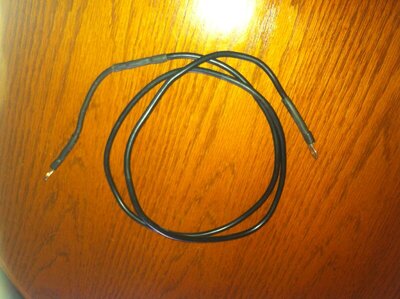
An alternator MUST be connected to a load while running, otherwise, the diodes will be damaged. This is the reason there is no fuse link in the output wiring. The problem with "fusable" link wire is: no real time - current melting curve data....or the time it takes to interrupt the current (and the degree of interruption) in AMPERAGE. Home made fuse links are marginal at best, depending on the exact length of wire is used, its AWG size and the termination used. Guessing, on the smaller diameter wire to use to protect a larger diameter wire or feed circuit, must be based on amperage AVAILABLE and the TIME it takes to stop the current flow....not on a "seat of the pants" estimate. Points to ponder.....
BOB RENTON
 
I have actually been working on something closely related to fusible links and battery charging. I have to be vague here because of nondisclosure.
The purpose of a fusible link is to prevent a fire. It is not intended to protect electronics. A typical specification for the fusible link to open circuit is:
1) At 110% of max load the link should open circuit in approximately 1 hour.
2) At 200% of max load the link should open circuit in approximately 20 seconds.
I've measured less than those specification in the circuit I'm designing. The 200% load was about 11 seconds.
Interesting that these fusible links are designed for open circuit at 200% load.

Your noted percentages and times are excruciatingly long in electrical equipment. Out of curiosity, why would consider using a fusable link rather than a more predictable fuse, be it a regular fuse, a time delay fuse or a current limiting fuse, for protection of a circuit or an individual component? How are you determining the available fault current and its supply voltage, be it AC or DC, and the obvious inductive or capacitive reactance constraints, without disclosing your application criteria?......unless cost is the driving factor.....
BOB RENTON
 
Auto Transport Service
Back
Top