• When you click on links to various merchants on this site and make a purchase, this can result in this site earning a commission. Affiliate programs and affiliations include, but are not limited to, the eBay Partner Network.

1972 Charger Electrical Issue

If removing the dash, I was made it with cluster attached. No need to remove the cluster to get the dash out, but since you already made it, doesn't matter anymore LOL. YOU CAN however preassembly the full dash on bench and mount the full assembly in one piece with all the wiring already attached, just like factory did.

Is it Rallye or Standard cluster?

It's late right now in Spain and I'm tired ( was driving for 8 hours ). Tomorrow will post more info.
 
It is the standard dash.

I set out to remove the cluster to troubleshoot why nothing except the speedo and the fuel gauge worked. I live in SE Georgia. Someone once used the expression, "Sometimes you set out to just drain the swamp a little, then you end up dealing with the gators". This is one of those times. I just wanted to repair a few wires, but now I am elbows deep.

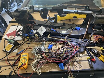
Anyway, I mapped out all of the wires. The main wire going to the cluster is pretty fried. I looked at the gauges and they all seem like they are in good shape, so hopefully it was just the wire that shorted. I also need to repair the wires that shorted out on Friday, but now that everything is out of the car, I will take care of that on the bench rather than laying on the floor under the dash.

I wrote down and mapped out all of the wires. I then used Lucid Chart to diagram them in a cleaner fashion and document what I need to repair. I cross referenced that with the wiring diagram that I found here and it all seems to match up. I am going to visually inspect all of the wires and then use an ohm meter to check any that look suspect. I have a ton of wire, pretty good soldering skills (Part of my job involves soldering connections on cell phone boards) and I think I can just replace the bad wires rather than spend $700 or so dollars on an entire loom. Actually after looking at the wiring harness, I am fairly sure that I could rebuild it if I had all of the connectors (I love classic cars for this reason).

Anyway, thanks for all of the help here. Keep the advice coming. I am not scared to death yet, I guess we will see how it goes when it is time to put it back together. I am hesitant to leave it in pieces too long. I took pics and made diagrams, but as more time goes by, I will forget where stuff goes.

Thanks again.
 
You can play this while you work on it:

:lol::drinks:
View attachment 1163744
Nacho is here so You are in good hands.:thumbsup: You got this. Keep the updates coming. Please post a pic of your cluster/gauges. I may have a new gauge or two for you.

upload_2021-9-6_8-19-12.jpeg
 
Well, I think I have all of the wires that were melted totally replaced. Where I could, I soldered in lengths of wire and the shrink wrapped the connections. Other places, I needed to entirely replace the wire. In looking at the scorch marks and burnt spots it looked like the red wire to the cluster shorted out a while ago. There was a wire tapped into it and the connection was just taped up. Everywhere I spliced or added wire I soldered, shrink wrapped and then checked continuity. So hopefully that works. Next issue here will be fitting all the wires back under the dash.

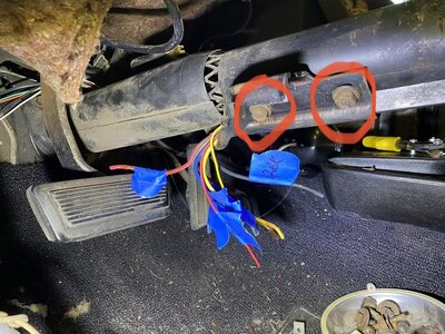
Now I am on to the wires the feed into the steering column. They seem mostly okay, but I want to make sure. If I take out the 4 bolts(highlighted in the pic) on the plate on the bottom of the column, will that allow me to follow those wires? If I take those out, will it cause me problems when putting things back together?

469E2D1F-AC38-4CEE-B02C-3B7D68113F89.jpeg 39FE7867-4FE7-4115-8EC6-671D47278A10.jpeg
 
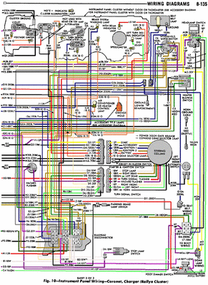
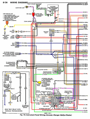
These two wiring diagrams have been huge in mapping this out. I have used it to trace every wire, and then used painters tape to label them. It’s tedious, but hopefully it works.

1FD5AA75-7AAE-41E3-91ED-97D93FCCA613.gif 642ABE2B-440B-4E17-BDB2-B8F76028F49E.gif
 
And another question;

the connector that fried is an 8 pin Mopar connector. I’m trying to find a source for that.

But, I was looking through my electrical chest and I have quality bullet connectors in sizes ranging all the way up to 10 gauge. I was wondering why I wouldn’t just use those? They would allow connecting/disconnecting, I could keep them separated better than the old connector did and it may be useful at times to disconnect on circuit individually.

thoughts?
 
Ignition switch 8-pin Molex connector? Anything would be better than those under current rated Molex terminals on the red and black wires. The factory by-passed them with Packards for the later/replacement switches. The Parckards are not much better however.


Ignition switch instructions.jpg
 
Ignition switch 8-pin Molex connector? Anything would be better than those under current rated Molex terminals on the red and black wires. The factory by-passed them with Packards for the later/replacement switches. The Parckards are not much better however.


View attachment 1163958
Yup, that one. I’m sure I could use any decent 12V connectors. Just curious what people have found to be the best way.
 
I used a bunch of bullet connectors 20 years ago.
Never had a problem.
You do need a good crimping tool.
 
Pictured are the PP15-45 housings (in white, appears factory somewhat). Individual housings interlock together, appears as one. The terminals are sized by wire size, PP15 (15 amp rated) on the smaller wires, PP30 (30 amp) for the 12gauge wires. Recommend the correct crimp tool for those.

I buy from here.

Thanks, I’ll check them out. The Mopar connectors leave something to be desired.
 
That’s interesting. Right away I didn’t notice the housings could be stacked. I was looking for a 8 pin terminal. Those are very interesting.

Thanks again,
 
Yes, those anderson powerpole conectors are very interesting. 72RoadrunnerGTX is who also show me those, and once stacked one it makes them look a bit stockish. I guess will make that upgrade someday in the future but as far I can keep the stock system plug in a decent operation conditions will keep them.

The diagram you are using is 73 Rallye cluster, which is a bit diff from standard cluster and it got small differences also with 72. For example, while cluster is feeded from ACC on Rallye setup, on Standard cluster the Cluster is feeded by the RUN circuit.

The best you can make is get the 72 FSM, which you can download from here:

https://mymopar.com/service-manuals/

72 Dodge Chassis service manual ( which is what gets the wiring diagram ) is not there, but Plymouth is there, and diagram will be the same for Dodge B body with Standard cluster.

Or get the repro printed paper version which I likes more ( nothing like the book on hands ). Originals used floats on sometimes too. Or CD-ROMs

https://www.ebay.com/sch/i.html?_fr..._nkw=72+Dodge+factory+service+manual&_sacat=0

Resto shops use to offer also these manuals on printed or CD-ROM versions.
 
Last edited:
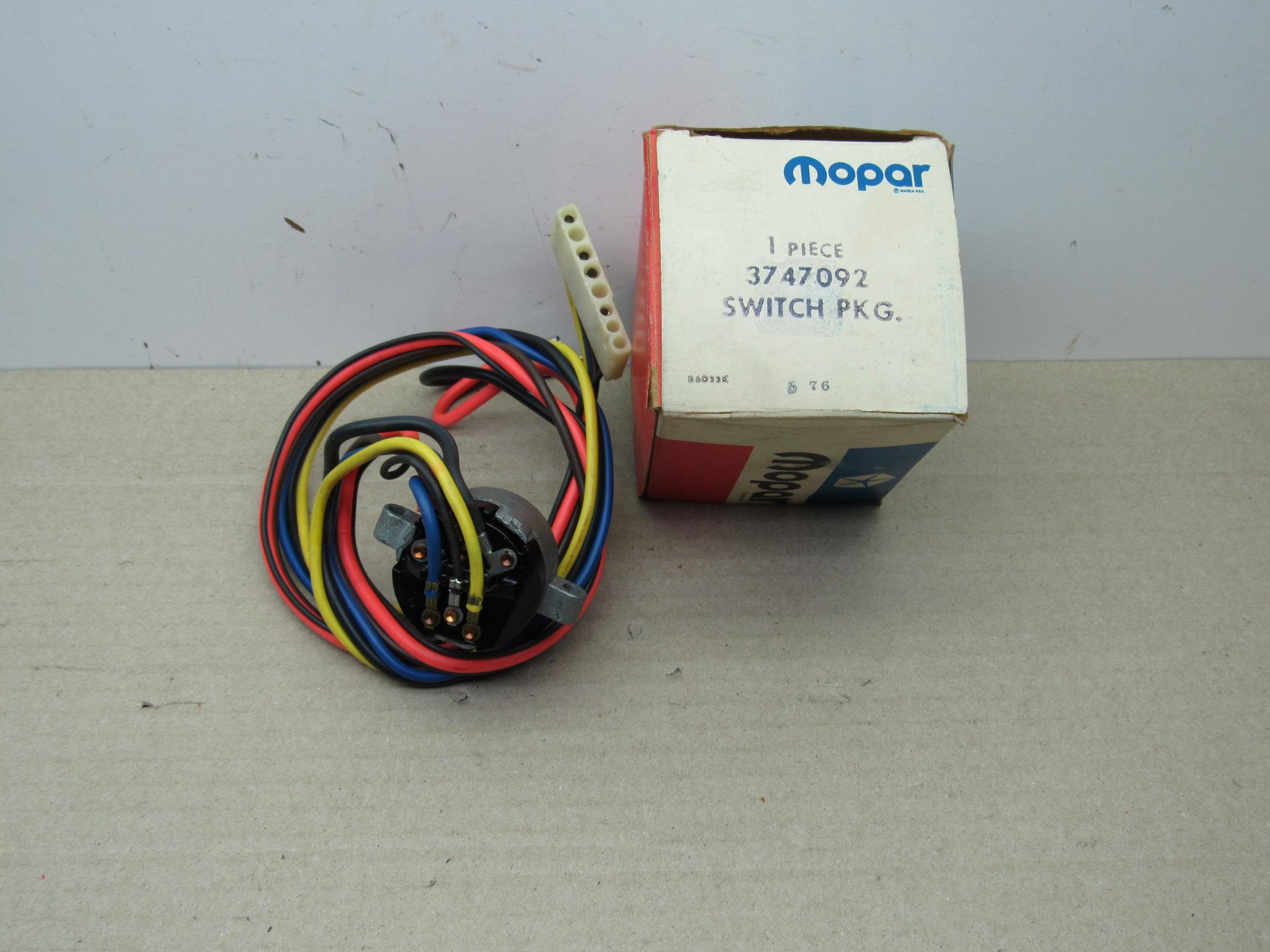
Oh! And about the ign switch wires, they are part of the ign switch assembly. So will be pulled out from top while the ign switch is removed

IMG_7255.jpg


Same applies for the turning switch harness.

If ign switch is in good conditions same as turning switch, just leave them in place and install terminals while harness is on car/column. Unless you want to make some column mantenience at the same time than making the wiring job.
 
The small 16 gauge yellow wire is for the ign key courtesy light and is separated from the rest of harnesses in column. It uses a regular packard 58/56 conector setup, which is plenty for that. No need for Anderson powerpoles for it.

The orange ( if column shifter ) and both reds for the key in buzzer function ( which becomes black on underdash harness ) doesn't need powerpoles conectors either, but if emulating the stock configuration stacking them into a "single" plug, well beter make them completelly on the powerpoles setup. These are not part of the ign switch assembly, but inserted into the same plug, being a standard equipment.
 
Last edited:
Auto Transport Service
Back
Top