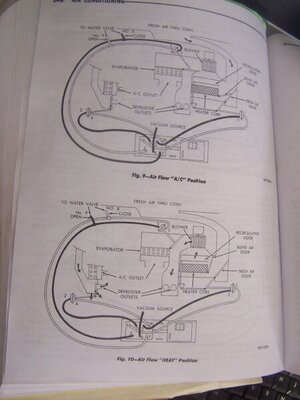
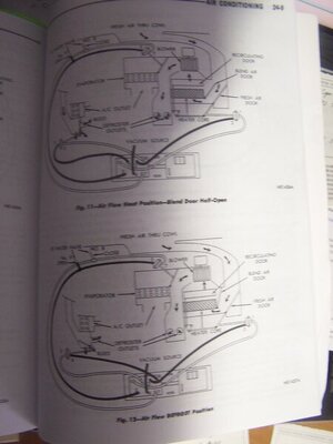
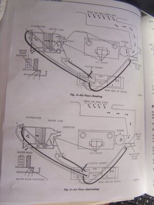
The a/c is working, although when I checked it late last summer, it seemed to be not as cold as it should be. Someone has monkeyed with this system before and I believe that i have everything hooked up properly now, with the only question being the vacuum hose on the delay. In spite of the red stripe on the short hose, is the vacuum line from the relay going to the right spot?
You are using an out of date browser. It may not display this or other websites correctly.
You should upgrade or use an alternative browser.
You should upgrade or use an alternative browser.
A/C time delay relay?
- Thread starter Richard Cranium
- Start date
Sixpactogo
Well-Known Member
I would say that it is. It's the same as mine. There are a few things that could be an issues though....It seems like these particular units are a little more complicated than they needed to be. I'm wondering if you heat valve is closing off completely when in AC mode. It could be a problem with the linkage on the heater door not shutting off that valve in the heater box completely. I had mine charged up late last fall and it was blowing real cold. However the temp outside was not real warm so I guess the Jury is still out on mine as well. Are you using R12 or 134?
Good old R12. 
Before I put the ductwork back in under the dash, with the center door open, you could reach in and feel that the heater tubes were still carrying some heat. The water control valve was rebuilt & I recently adjusted that cable, so we'll see if that takes care of that issue.

Before I put the ductwork back in under the dash, with the center door open, you could reach in and feel that the heater tubes were still carrying some heat. The water control valve was rebuilt & I recently adjusted that cable, so we'll see if that takes care of that issue.
JimKueneman
Well-Known Member
134a blows 34F if you pull the EPR valve out. I did not put the cycling switch in to compensate with the EPR removal. I understand what freeze is and I just shut it off and cycle it by hand when I detect it start to freeze up.
Still R12, wow it's been a long time since that stuff was gone.(still the best tho)
I acquired a NOS 30 pounder sever years ago & I also have about a dozen small 16 oz(?) cans.
Sean brady
Member
I am looking for the vacuum diagram for a AC 68 charger. The service book I have, shows the basics but it does not show the vacuum line going to the time delay relay or which lines need the "restrictor" in them. I have found one diagram that show the restrictors in the both lines going to the same actuator (I believe the AC outlet door - vacuum lines 5 and 7). The picture above with the "T" in it going to the recirculating air inlet actuator (vacuum line 3) looks like it has a restrictor in it. Any help would be appreciated. Are the restrictors needed?
JimKueneman
Well-Known Member
I am looking for the vacuum diagram for a AC 68 charger. The service book I have, shows the basics but it does not show the vacuum line going to the time delay relay or which lines need the "restrictor" in them. I have found one diagram that show the restrictors in the both lines going to the same actuator (I believe the AC outlet door - vacuum lines 5 and 7). The picture above with the "T" in it going to the recirculating air inlet actuator (vacuum line 3) looks like it has a restrictor in it. Any help would be appreciated. Are the restrictors needed?
you using the factory manual? I’m sure that info is in there with a vacuum diagram. MyMopar.com has pdfs of the manual
mopar 3 B
Well-Known Member
Make sure you use the Dodge manual. The Chrysler/Plymouth is slightly different.
Sixpactogo
Well-Known Member
I am looking for the vacuum diagram for a AC 68 charger. The service book I have, shows the basics but it does not show the vacuum line going to the time delay relay or which lines need the "restrictor" in them. I have found one diagram that show the restrictors in the both lines going to the same actuator (I believe the AC outlet door - vacuum lines 5 and 7). The picture above with the "T" in it going to the recirculating air inlet actuator (vacuum line 3) looks like it has a restrictor in it. Any help would be appreciated. Are the restrictors needed?
Not sure what you are referring to as "restrictors" but there are no restrictors in any of the vacuum lines that I am aware of.
JimKueneman
Well-Known Member
Not sure what you are referring to as "restrictors" but there are no restrictors in any of the vacuum lines that I am aware of.
there were 2 restrictors on 2 lines on my 68 Coronet
Sixpactogo
Well-Known Member
Do they show up on the diagram showing the vacuum hoses? My service manual shows the door positions in all of the switch positions but I see no restrictors. Only the actuators that operate the doors. Maybe we are not on the same page.
JimKueneman
Well-Known Member
Do they show up on the diagram showing the vacuum hoses? My service manual shows the door positions in all of the switch positions but I see no restrictors. Only the actuators that operate the doors. Maybe we are not on the same page.
the one I looked at back then did.
Sixpactogo
Well-Known Member
Sixpactogo
Well-Known Member
Sean, are you referring to the picture in post 16? If so, what are you calling a restrictor?The picture above with the "T" in it going to the recirculating air inlet actuator (vacuum line 3) looks like it has a restrictor in it. Any help would be appreciated
JimKueneman
Well-Known Member
was in the text not diagram. The only reason to care about that relay (it not what you think of as a relay it is a pancake looking thing in the bottom of the box above the passengers feet) is if it was stuck closed and the AC clutch won’t disengage. Mine is open all the time so it was a don’t care. It was a sale brochure feature and likely never really did a whole lot.
Sixpactogo
Well-Known Member
I agree that the delay really didn't do much to start with. I could never figure out how it worked but my compressor would run for a while in defrost mode then shut off so I guess it works to some extent. I never noticed any restrictions in those two short hoses but maybe they are there. I guess it really don't matter much to me since I seldom use the defrost mode anyway. Thanks for the clarification on restrictors.View attachment 1235631
was in the text not diagram. The only reason to care about that relay (it not what you think of as a relay it is a pancake looking thing in the bottom of the box above the passengers feet) is if it was stuck closed and the AC clutch won’t disengage. Mine is open all the time so it was a don’t care. It was a sale brochure feature and likely never really did a whole lot.
LowBikeMike
Well-Known Member
The time delay relay is controlled by vacuum. The attached hose pulls a vacuum internally in the relay, when the vacuum is great enough the electrical contacts are forced open by the lid pushing down on them and power to the compressor is interrupted. I've played with the one on my car and generally it cuts power in about 3-4 minutes. Not sure where the 10 minutes comes from.
- Local time
- 1:36 PM
- Joined
- Jul 1, 2015
- Messages
- 6,472
- Reaction score
- 8,081
IMO....According to my service manual, it looks like I'm missing this.....
View attachment 407708
What's this relay do & has anyone got one to sell, or have any ideas about a substitute?
I think it depends on if its an ON DE LAY or OFF DELAY. I believe its to operate the A/C compressor for a predetermined period of time (OFF DELAY) to DEHUMIDIFY the air flow before directing the air flow to the windshield, to prevent fogging. This is totally different than the pressure cycling switch to regulate the suction pressure of the A/C evaporator to prevent icing on newer vehicles....like GM's CCOT system.(Cycling Clutch Orifice Tube).
BOB RENTON
Starting your own WTB thread is a good starting point.Any help would be appreciated.
Similar threads
- Replies
- 0
- Views
- 297


