• When you click on links to various merchants on this site and make a purchase, this can result in this site earning a commission. Affiliate programs and affiliations include, but are not limited to, the eBay Partner Network.

Door jamb switch wiring

velrob

Well-Known Member
Local time
10:31 AM
Joined
Jan 15, 2016
Messages
603
Reaction score
110
Location
toronto
I'm looking at wiring diagram for my car

71 charger 383

I see two wires coming from the door jamb switch meanwhile I only see one spot on the switch itself

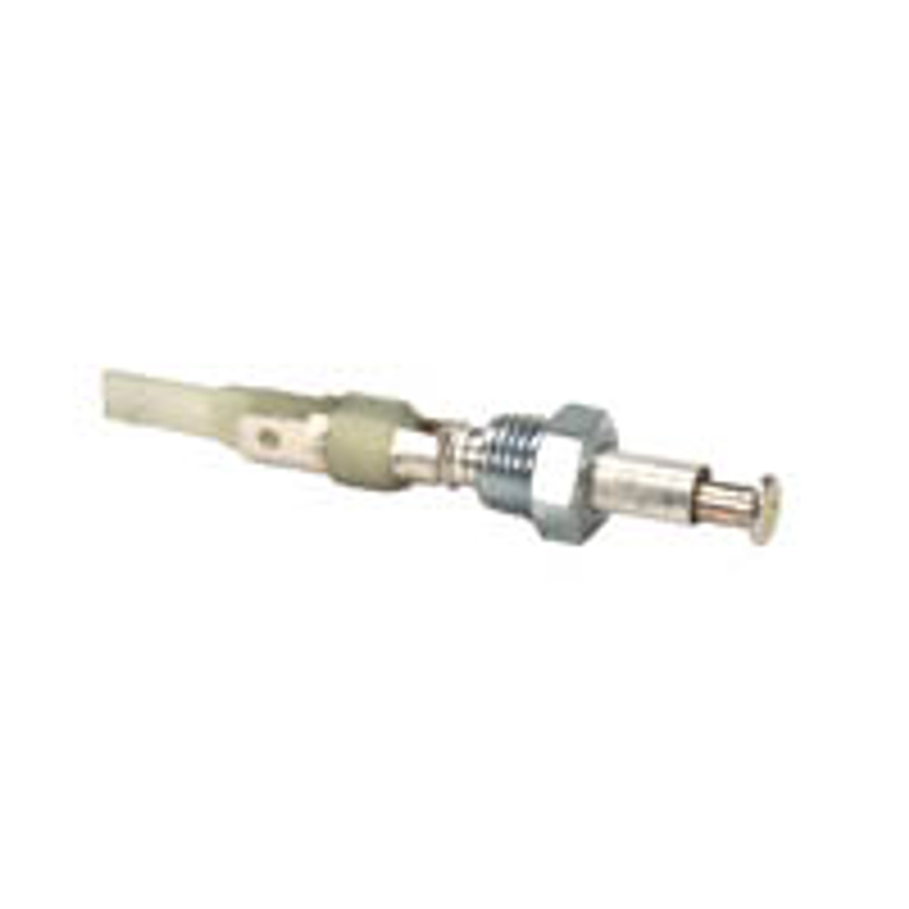
How exactly are these things wired?

Ive uploaded a picture of my switch and the wiring portion of the diagram

IMG_20190521_135254.jpg IMG_20190521_135307.jpg
 
It will be a Y connection. One comes from the harness. Then it Y's off one goes to the left door one goes to the right door. The switches themselves get their ground from the body.
 
But there should be two wires that connect to the switch itself. On my diagram it shows the secondary line goes to the buzzer. It doesn't show it as Y to both switches
 
There is only ONE terminal on that switch. There is no possible way to connect more than 1 wire to it unless you have a Y harness. The terminal is the post itself.
 
Wrong switch. That's an early switch. Not sure when they went to the two wire door switches, but I'm thinking 70-71.
 
Wrong switch. That's an early switch. Not sure when they went to the two wire door switches, but I'm thinking 70-71.
Ahh see i learned something there... I knew the switch he posted was the same as the ones up to atleast 69.
 
Ah crap thanks. I found the two wire switch.
 
it is called a splice in the auto repair world. knowing the circuit as a working tech under stand that further up the wire will be the second / splice wire. the door switch is a ground for the dome and interior lighting. witch is the yellow wire the second yellow with a tracer color is for the other side so the dome and other lights have power all the time when you open the door it grounds the circuit and boom the lights come on.the pink is the power to all interior lights
 
Ya thanks got that part lol

Wasn't sure about the jamb wiring since it only had one bullet connector
 
Then since 72s got two prongs.

And there is a reason wasn't used anymore the single terminal switch, keep isolated the common ground for dome light from the warning system ( seatbelt, key, lights on ) ground.


EDITING FOR MORE INFO
In that way, the buzzers won't be activated with passenger side door ground ( linked to dome light ), just with driver side ground. Buzzers are designed just to work to driver.
 
Last edited:
'72 would have a 3-pin switch on the driver's door and a two pin switch on the passenger side.
Weird, I always have known just 71s were 3 pins. Maybe earliers 72s too? I have found on all 72s I have "worked" being 2 prongs on driver side.

Aside that, 3 pins setup can become in two prongs setup easilly. As far dome light ground wire ( yellow ) keeps separated from the rest ( black ) will work perfect.
 
Last edited:
'71 and '72 use the same pin switch configuration. Yellow wire-dome lamps, both doors. Yellow with trace wire-time delay relay trigger, both doors. Black wire-key in switch & headlamp on buzzers, driver’s door only.

Never seen a ’72 with a 2-pin switch on the driver’s door, no indication of a 2-pin driver’s door switch in the ’72 wiring diagrams either.


DSC06548.JPG
DSC06551.JPG
DSC06552.JPG
 
Last edited:
1971 dodge charger SE 383
I have the same issue with my wires . Can someone tell me what these wires are and where do they go to ?
I included photos :

Thanks
Ried71

thumbnail_IMG_1080.jpg thumbnail_IMG_1082.jpg thumbnail_IMG_1083.jpg
 
Pic one:
Door jam switch( round with 3 pins )
Rear deffog pigtail ( t shaped plug )
Emergency brake ( black bullet terminal )

Can't think the other three... maybe power windows related?

Second pic:
Ignition module ( added since all 71s were still points )

Third pic:
regulator plug
 
Auto Transport Service
Back
Top