Awhile ago someone posted a spec sheet with all of the critcal measurements regaurding the main structure of a 69 B body. Problem is I can't remember who or where. I'm thinking Matt, Will, or Donny but the page is eluding me. I am about ready to start removing some major parts on a 69 Charger and would like a baseline before I start. Does anyone remember this or know where to find the dimensions?
You are using an out of date browser. It may not display this or other websites correctly.
You should upgrade or use an alternative browser.
You should upgrade or use an alternative browser.
Frame rail and main structure measurements
- Thread starter hunt2elk
- Start date
Jeremiah
Well-Known Member
http://www.moparts.org/Tech/Archive/paint/11.html
Man, I sure don't miss WI salt rust....
- - - Updated - - -
And one more for good measure...

Man, I sure don't miss WI salt rust....
- - - Updated - - -
And one more for good measure...
- - - Updated - - -
Man, I sure don't miss WI salt rust....
The car was originally from Michigan and licensed to 1982, but had thick grease squirted in the doors and rockers. It looks like this had been done shorty after new because the rust issues are not that bad from salt. The frame rails, rockers and torsion bar crossmember look perfect on the exterior but are corroded from the inside as a result of being filled with mouse nests and sitting so long. I will have to start a resto thread when I get some extra time.
mopar4don
Well-Known Member
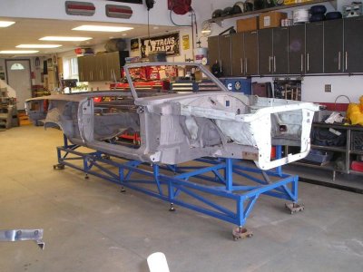
I have my charger sitting on my body jig and I have a problem.
As per the frame dimension sheet above, the front of the car is up (to tall) 1/2 of inch
The back of the car is 1 inch to short (back end needs to go up)
Should the front suspension be mounted when doing this?
Anyone have any suggestions?

The back of the car will be heavier when it is stripped down like you have it. How far off is it when you pull the front down? How were the quarter-door-fender gaps? Do you see any bends or kinks in the frames or rockers?
mopar4don
Well-Known Member
The back of the car will be heavier when it is stripped down like you have it. How far off is it when you pull the front down? How were the quarter-door-fender gaps? Do you see any bends or kinks in the frames or rockers?
I did pull the front down into position. It helped the rear dimension but I don't recall what it was.
I will have to recheck. I thought that the center 6" dim in those two locations was more critical, that's why I left it there.
I didnt check the door gaps as my doors sag (another problem)
The the frame rails and rockers look good no bends or kinks.
What are you thinking?
Well I wouldn't be welding in any frame connectors or torque boxes yet - just kidding.
I would rachet strap the front down and see how the other measurements compare to the specs. front to back and side to side. I can't imagine it being as bad as you think because you would have noticable damage somewhere. Did you make that jig or is it the one from SGTPaul who made it for his 68 Charger?
I would rachet strap the front down and see how the other measurements compare to the specs. front to back and side to side. I can't imagine it being as bad as you think because you would have noticable damage somewhere. Did you make that jig or is it the one from SGTPaul who made it for his 68 Charger?
- Local time
- 1:36 PM
- Joined
- Jul 17, 2008
- Messages
- 4,751
- Reaction score
- 2,504
- Location
- Southeastern, PA
Where are you measuring these points to ? In other words, did you build the jig to the chart first and then mount the car or did you use another method ?
mopar4don
Well-Known Member
Defiantly not ready for those frame connectors and torque boxes just yet!
Now just to clearify, Right now it is sitting on brackets on the front leaf spring mount, It is also sitting on square tubing that goes left to right on the car at the torsion bar cross member. Both of these "points" are the 6 inch spec in the drawing. If I ratchet the front down, then the car would pivot at the torsion crossmember point, the rear leaf spring point would get slightly bigger, (which would be about 6 1/8) and the back point should get closer to spec.
Is this what you mean?
I made the jig, it originally was a 4x8 foot table that I picked up at a local scrape yard. I cut it in half horizontally to give me the 4x16. about a week after I got it SGT Paul offered me his.
Oh well I'm havin fun.
- - - Updated - - -
I built the jig

Then set the car on it. I used strings on top of the jig the entire 16 foot length. I leveled it with 1/2 threaded rod at each corner and leg. I verified that it was flat by using a laser, and level using my trusty 6 foot bubble level.
From there I transfered the line to the side of the jig. Then adding another string, this way I can tell if the jig moves simply by sighting in the string line.
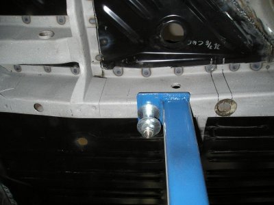
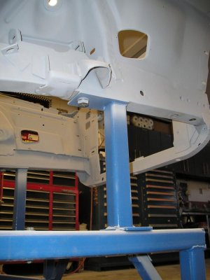
In this picture you can see the string and the two pieces of square tubing that the car is actually sitting on. In my case the 6 inch dimension is really 3 5/8
Hope I explaned it so you can understand.

Now just to clearify, Right now it is sitting on brackets on the front leaf spring mount, It is also sitting on square tubing that goes left to right on the car at the torsion bar cross member. Both of these "points" are the 6 inch spec in the drawing. If I ratchet the front down, then the car would pivot at the torsion crossmember point, the rear leaf spring point would get slightly bigger, (which would be about 6 1/8) and the back point should get closer to spec.
Is this what you mean?
I made the jig, it originally was a 4x8 foot table that I picked up at a local scrape yard. I cut it in half horizontally to give me the 4x16. about a week after I got it SGT Paul offered me his.
Oh well I'm havin fun.
- - - Updated - - -
Where are you measuring these points to ? In other words, did you build the jig to the chart first and then mount the car or did you use another method ?
I built the jig
Then set the car on it. I used strings on top of the jig the entire 16 foot length. I leveled it with 1/2 threaded rod at each corner and leg. I verified that it was flat by using a laser, and level using my trusty 6 foot bubble level.
From there I transfered the line to the side of the jig. Then adding another string, this way I can tell if the jig moves simply by sighting in the string line.
In this picture you can see the string and the two pieces of square tubing that the car is actually sitting on. In my case the 6 inch dimension is really 3 5/8
Hope I explaned it so you can understand.
- Local time
- 1:36 PM
- Joined
- Jul 17, 2008
- Messages
- 4,751
- Reaction score
- 2,504
- Location
- Southeastern, PA
When I made my jig, I built the supporting points to the frame chart and set the car down on it. Mind you, I'm working on a convertible which is a flexible flyer of the highest order but it wasn't as off as your car appears to be.
You've got a good handle on paying attention to the frame being level and having a datum line to reference to which is important. Not to be insulting, but are you supporting the car and measuring from the exact points on the chart ?
You've got a good handle on paying attention to the frame being level and having a datum line to reference to which is important. Not to be insulting, but are you supporting the car and measuring from the exact points on the chart ?
Attachments
mopar4don
Well-Known Member
Yes I am measuring to the exact points as I understand them.When I made my jig, I built the supporting points to the frame chart and set the car down on it. Mind you, I'm working on a convertible which is a flexible flyer of the highest order but it wasn't as off as your car appears to be.
You've got a good handle on paying attention to the frame being level and having a datum line to reference to which is important. Not to be insulting, but are you supporting the car and measuring from the exact points on the chart ?
(J) The rear point 16-7/8 from datum line to center of the rear shackle mounting hole
(X) Just forward of the rear spring mount is a datum hole, (in bottom view this is the 36 3/4 dim) from this datum hole at the bottom of the rail to the datum line is 6"
(X) Just forward of the T-bar crossmember is a datum hole, at this point, 6" from the bottom of the rail to the datum line
(A) The front of the car, 13-5/8 from the bottom of the rail (at the datum hole) to the datum line
Is this right?
Mopar4don,
it seems that you are correct in all your measurements and levels...that being the case I can only assume something either happened at the factory OR the car has moved since it was delivered ! (chassis twist from racing?)or your levels are off.
Maybe check a few more measurements between the floor pan (centre .both right and left)compare all.
whats the exact measurement in the middle of the rocker as compared to each end?
also i can offer this from SGTPaul's resto in post # 73 .
"Dolly is all built now and car on it. Yes I had a few things to address. My front frame rails are slightly high but I believe that will lock into place after installation of the surrounding sheet metal and floor. The rear frame rails were about ¼” too low so I cut them out (again ) and put them back where they were supposed to be. "
He did replace the rear rails then found he was a bit low.So who know where they where originally? maybe like yours...
EDIT..Have you put a level on the door sill ?is it level?
considering the jig is level and you have 2 six inch blocks the(sill) should also be level!
CharGer
Well-Known Member
In regard to the rear frame rails not meeting the dimensions of the chart, what is the dimension to the point above the axle? If that dimension is also short then I would try jacking up the rear to get the dimension you need and then see if that axle measurement is correct. My cars rear frames had to go up because I measured incorrectly and that was validated by the measurement above the axle. Now it is right on.
- Local time
- 1:36 PM
- Joined
- Jul 17, 2008
- Messages
- 4,751
- Reaction score
- 2,504
- Location
- Southeastern, PA
Yes I am measuring to the exact points as I understand them.
(J) The rear point 16-7/8 from datum line to center of the rear shackle mounting hole
(X) Just forward of the rear spring mount is a datum hole, (in bottom view this is the 36 3/4 dim) from this datum hole at the bottom of the rail to the datum line is 6"
(X) Just forward of the T-bar crossmember is a datum hole, at this point, 6" from the bottom of the rail to the datum line
(A) The front of the car, 13-5/8 from the bottom of the rail (at the datum hole) to the datum line
Is this right?
Yep, you're spot on. What I would do iffen I were you - is to build your upright supports, but don't weld them to your jig just yet (more on this later). Attach them to the specified points on the frame rails and lower the car onto the body of the jig. The car will most likely settle into this position and once you double check your measurements, weld the uprights to the jig. What I think is happening is your car has sprung because it's only being supported in the middle. It's not serious as you see this everytime you lift a car up by the k frame. As you jack a car up, watch the gaps between the door and fender and the hood and cowl. They close up before the wheels even budge. Unibodies are like spaghetti, they bend pretty far before you do any damage.
Right now, your car is not in a natural state. It's not supported like the frame chart would have it and it's not sitting on it's wheels so all bets are off as to whether or not it's tweaked.
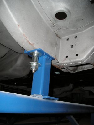
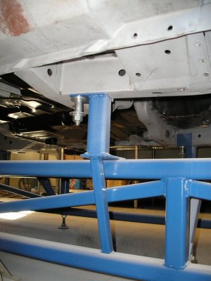
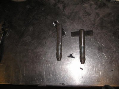
My uprights are square tubing with a piece of angle iron on the top. This mount (angle iron) has a 1" hole in it for attaching the frame rail. I made 5/8" T bolts to fit into the existing factory holes so the car can be easily mounted and dismounted. If you weld the uprights first, you must be spot on as to the location of the holes in the frame rails and as we all know, Ma Mopar wasn't always terribly consistent. Just because they should be, don't mean they are.
This is the reason you bolt the uprights to the car, lower it into position and then weld them home. It may take a little while for the car to settle into position, but if it is indeed off by an inch, it'll show up here. I hope this is clear - it's easy to grasp when you see it, but tough to 'splain.
Attachments
mopar4don
Well-Known Member
Hi Elk,
Yes, my front 6" mounting point is just forward of the T-bar crossmember.
If you look at post #9 in the 1st picture, the car is sitting on square tubing rails which are on jackstands.
These rails are at 51 1/8 apart at the datum holes marked X on the spec sheet.
- - - Updated - - -
5wndwcpe,
You explained it perfectly! I was wondering if this is whats happening.
Do you have any pictures showing your front mounts with the 5/8" T bolts. not sure I follow how you are bolting it down.
What about the back mounts, Is the rear frame rail just sitting on on the mount or is it bolted or clamped? Do you have any pictures of this?
Thanks for your help
Yes, my front 6" mounting point is just forward of the T-bar crossmember.
If you look at post #9 in the 1st picture, the car is sitting on square tubing rails which are on jackstands.
These rails are at 51 1/8 apart at the datum holes marked X on the spec sheet.
- - - Updated - - -
Yep, you're spot on. What I would do iffen I were you - is to build your upright supports, but don't weld them to your jig just yet (more on this later). Attach them to the specified points on the frame rails and lower the car onto the body of the jig. The car will most likely settle into this position and once you double check your measurements, weld the uprights to the jig. What I think is happening is your car has sprung because it's only being supported in the middle. It's not serious as you see this everytime you lift a car up by the k frame. As you jack a car up, watch the gaps between the door and fender and the hood and cowl. They close up before the wheels even budge. Unibodies are like spaghetti, they bend pretty far before you do any damage.
Right now, your car is not in a natural state. It's not supported like the frame chart would have it and it's not sitting on it's wheels so all bets are off as to whether or not it's tweaked.
My uprights are square tubing with a piece of angle iron on the top. This mount (angle iron) has a 1" hole in it for attaching the frame rail. I made 5/8" T bolts to fit into the existing factory holes so the car can be easily mounted and dismounted. If you weld the uprights first, you must be spot on as to the location of the holes in the frame rails and as we all know, Ma Mopar wasn't always terribly consistent. Just because they should be, don't mean they are.
This is the reason you bolt the uprights to the car, lower it into position and then weld them home. It may take a little while for the car to settle into position, but if it is indeed off by an inch, it'll show up here. I hope this is clear - it's easy to grasp when you see it, but tough to 'splain.
5wndwcpe,
You explained it perfectly! I was wondering if this is whats happening.
Do you have any pictures showing your front mounts with the 5/8" T bolts. not sure I follow how you are bolting it down.
What about the back mounts, Is the rear frame rail just sitting on on the mount or is it bolted or clamped? Do you have any pictures of this?
Thanks for your help
- Local time
- 1:36 PM
- Joined
- Jul 17, 2008
- Messages
- 4,751
- Reaction score
- 2,504
- Location
- Southeastern, PA
Sweet pictures, thanks
Cool beans, I hope this helps. The front mounts are just flat plates with bolts using the k frame holes. Keep in mind, the frame rail is pitched up in this area so your mount needs to do the same.
mopar4don
Well-Known Member
Cool beans, I hope this helps. The front mounts are just flat plates with bolts using the k frame holes. Keep in mind, the frame rail is pitched up in this area so your mount needs to do the same.
So your front mount is actually is the 12 3/4 dimension or "B"dim on the sheet?
What about the rear mount? Is the rear frame rail flat or does it have a slope?
Did you subtract the distance from the bottom of the rail to the center of the shackle pin from the "J" dimension or 16 7/8?
- Local time
- 1:36 PM
- Joined
- Jul 17, 2008
- Messages
- 4,751
- Reaction score
- 2,504
- Location
- Southeastern, PA
So your front mount is actually is the 12 3/4 dimension or "B"dim on the sheet?
Correct. It's not the hole for the bolt but rather the back edge of square tube that measures 12 3/4" to the datum line.
Similar threads
- Replies
- 8
- Views
- 504
- Replies
- 14
- Views
- 2K
- Replies
- 60
- Views
- 4K
- Replies
- 17
- Views
- 941
- Replies
- 16
- Views
- 1K


