• When you click on links to various merchants on this site and make a purchase, this can result in this site earning a commission. Affiliate programs and affiliations include, but are not limited to, the eBay Partner Network.

Garage 360 build, how I do it

dvw

FBBO Gold Member
FBBO Gold Member
Local time
5:34 PM
Joined
Feb 16, 2010
Messages
7,748
Reaction score
13,241
Location
waterford mi
A lot here who haven't built an engine or hop up their ride with minimal experience. Some that are thinking about it. Thought it might be good to see it step by step. My background. In the auto repair business in one way or another since 1974. At one time or another have worked on every aspect of the car. This particular engine is a used 360 Magnum. Brand new It was converted to a carb added headers and installed in an 83 D100. Ran well, one trip to the track 14.80s with a full fiberglass cap. Then at very low miles a nut was dropped down the carb. It required 1 sleeve .030" over and was back un service. Truck was wrecked. The motor removed and was going to go into a Dart. That was about 15 years ago. It was taken apart and sat. It got a little rusty setting. I had a customer wanting to hop up his 318 68 Satellite convertible. So we decided a 360 magnum would be an easy upgrade. I rebuilt the 994 using a low gear set to complement the 3.23. So follow along with the engine build. This is the starting point
Doug
20191207_101734.jpg
n
 
The block was cleaned with steel shot tumbled. Then touch honed in the bores and lifter bores. Deck square was checked. Both sides were within .002" front to back and .004" from side to side. Since the short block was realitivly fresh at the time it was removed the decision was to run pistons, rods, rings. For the $350 price tag is came with in the box cam, rod ,and main bearings. The 1st hiccup was the rod journals were still pitted after the crank was polished. So the rod journals were turned .010" the piston and rod assys were cleaned. The roller tappet were disassembled and cleaned. External bolts sandblasted and painted.
Doug
20200212_171246.jpg
20200215_161041.jpg
20200212_171259.jpg
 
Last edited:
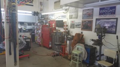
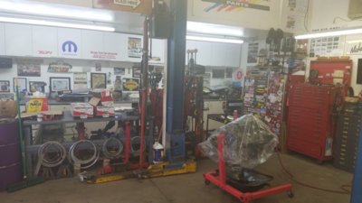
Then you have to have a place to work. My wife's brothers, my sons, and I built this shop in 2003. 24×40. As big as the township would allow. Doug
20200216_115003.jpg


20200216_115026.jpg

20200216_115017.jpg
 
Nice start Doug,

What is the goal for the 360? Back to stock performance or a wild build?
What did the 360 do from factory in hp?
 
It will have 9.3-1 compression, Edelbrock heads, Edelbrock Performer RPM , Comp XR274HR-10 cam. Headers, 2/12" exhaust, Edelbrock 600 carb from the old engine. No dyno, this is a street cruiser. My bet is it would dyno well over 400hp. Budget build, thus the used short block and bolt on parts.
Doug
 
Like you I have done many over the years on a budget. We always called them "High School Rebuilds " I still do'um to this day.
 
pitts? you mean the oil resouviours?
looks good
do those heads have shaft of Magnum rockers?
 
Yes, oil reservoirs. It was the owners wish to turn it. Stud rockers Comp 1.6
Doug
 
So special tool #1. Youll need an engine stand. Get a sturdy one. Especially if it's a big block. If your going to knock off any casting flash, do any clearancing, oil flow mods, now is the time. Run a thread chaser though every bolt hole. This build stock is ok. Make sure all the block plugs are out. Refer to a diagram or service manual. The SB has a hidden plug down the oil pump feed hole. As weve all been told . Clean, Clean, clean. Tide and hot water. Then blow dry , followed by WD40 to prevent rust. The block in the previous post looked clean. I use white paper rags from Sam's Club. After washing use trans fluid on the rag in the bores. When it comes out red without black it's ready. See rag below. Still getting black. Should look totally red. Special tool #2. You'll need a few long brushes lit go down all the oil galleries. Most of you will have the machine shop install cam bearings as you dont have the tool. Test fit you cam NOW. Check that the oil holes in the bearings that have them line up with the galleries. Use a long blot in the end as a handle. Slowly insert it. Does it spin by hand? Your good. If not look for shiny spots on the individual bearings. They will have to be scraped at those areas. It tedious and will take multiple attempts. After I installed the bearings this cam fit perfect. A little sealer on the core plugs. Use a socket that fits and knock them in. Make sure they're square. Just past the chamber in the block hole is far enough. Teflon on the threaded block plugs. A little is fine . Dont overdo it and make a mess. Or worse contaminate your clean gallery with goop.
Doug
20200216_114752.jpg
 
Last edited:
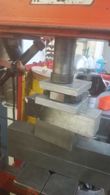
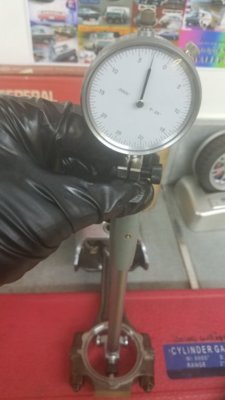
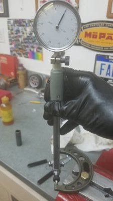
So now with everything clean we're ready to measure. Measure every journal in 4 spots. Towards each end and at 90 degrees. Write each down. Now install the main and rod bearings and torque to spec. Hold the rod across the cap to keep it from twisting. I use my press with a couple pieces of aluminum. Vice will work with aluminum as well. I zero the bore gauge based on the previous rod, then main readings. Insert the dial bore in the bearing to measure. Do the math and you have your clearance. You dont have dial bore or mic? Good old plastigauge. If using plastigauge the item being checked should be installed dry. Do not rotate the crank. A little wd40 wiped on the bearing surface will keep the plastigauge from sticking. The plastigauge should be the same width across the journal. A good rule of thumb for clearance is .001/inch of journal diameter. .001" looser doesnt scare me. .001" tighter scares me.

20200215_162931.jpg 20200215_171953.jpg 20200215_163208.jpg
 
Last edited:
time to bottom tap the threads and drill the main oil feeds to 9/32
some are quite bad from the factory
I've found broken drill tips, incomplete drills (drill sharpened one to many times and too short) etc
if stick shift post back
see the debate on front oil galley plugs
I drill them and the cam thrust plate to blead air out of the mains and oil the chain
others don't
 
Wrmrider brings up a great point. Dont just blow air or brakleen through the holes. It needs to be a stiff brush piece of tubing, reamer. A sad story for a buddy of mine. New build. Spent over $15k in parts. Spit a rod on the 6th pass. Brand new Eagle crank and rods. #3 turned as black and crusty as a barbeque grill grate. #2 was fine, same block oil feed passage. He swore the rod clearance was correct. He asked what did I think? I said the crank oil feed must be blocked. He said how? I said I dont know, broken drill bit end mill or something? We pulled the crank and a broken end mill fell out of the oil feed hole to the rod. I asked him if if cleaned the crank. He said "ya, I sprayed brake clean thru it, brush it? nope".
Doug
 
Last edited:
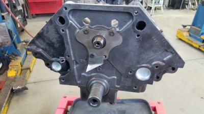
On to the crank and cam install. Lay the bearing shells (the side with the oil holes) in the block. Dont forget the rear main seal (lip facing towards the inside of the engine). Lube them up.drop the crank in. I like anaerobic sealer at the rear main cap. I apply it from the edge of the main seal out to the edge of the cap. Preventing any oil seepage between the cap and the block. Drop the caps on. Tang facing tang. Hand start the bolts with oil for stockers or supplied lube with aftermarket bolts/studs. Take soft face hammer and seat all 5 caps to the block. Snug all the bolts. Then torque to a low spec, 30lb/ft. Then final torque to factory or supplied torque from the fastener supplier. Crank should spin freely. Cam goes in next. Use long bolt as a handle. Lube the thrust plate an torque the bolts. Now temporarily install the chain and sprockets. We'll torque the cam bolt after degreeing the cam. Start dot to dot. You'll know if it's close by dropping lifters into #6, #1. With the dots lined up the intake and exhaust should be very close to level with each other(same amount of lift). If not, you probably used the wrong mark on a multi position crank gear. Temporarily install #1 piston with rod bearings but no rings. Cover the rod bolts with rubber sleeve to prevent nicking the crank. Install the cap with a little oil on the bearing. Tang to tang. Just snug the rod bolts.. Next is degreeing the cam. Install the degree wheel and eyeball the pointer to zero with #1 piston at tdc. Install a a piston stop. Rotate the motor in each direction until it contacts the stop. Record the two readings from the degree wheel. They should be the same. If not add the numbers and divide by 2. Example; you get 16atdc and 4 btdc. 4+16=20/2 = 10. With piston contacting the stop move the pointer to 10. Now check again. Repeat until the number at atdc and btdc are the same. Your pointer now reads Zero at true tdc. Measuring the cam is next.
Doug
20200215_141604.jpg
20200214_164018.jpg
20200215_112347.jpg
 
Last edited:
20200215_135049.jpg
ju
20200215_141612.jpg
Now it's just a matter of setting the dial indicator. Square the shaft of the indicator to the #1intake lobe (remember on a mopar wedge the first lobe is exhaust. Use the 2nd lobe back) . I use an extension screwed into the indicator to reach. Now slowly rotate the engine clockwise stopping just as the indicator reads .050" record the number of degrees. Then go to full lift and back down to .050" when you get near the
050" mark go very slowly. Now compare to your cam card. In this case the desired opening and closing points were dead on. This cam is ground 4 degrees advanced and settled in at 106 c/l. If it was off you could advance or retard by using the multiple slots in the lower gear or an off set key in the cam. It's good so we'll remove the cam bolt , locktite and torque it.
Doug
 
Last edited:
Do you weigh each individual piston/rod assembly and check for weight differences?
Is it worth checking and lighten the individual parts to match the lightest assembly on a stock/mild performance build?
Guess it would not harm, but just wondering what or if there is a certain tolerance to this?
 
On a race engine yes. On this engine no. Factory balance is close enough. This will be a street engine that will seldom see 6000 rpm. The money was spent on heads, intake, cam, and rockers. There is $750 in parts and machine work for the short block.
Doug
 
Last edited:
So now we're ready to install the rings. The piston to wall is measured by the same method as the bearings, mic and dial bore. Checking ring gap . Square the ring in the bore about 1" down. A combination square makes it easy pull the ring up against the square at N E S W around the bore until it touched the square. Now measure the gap with a feeler gauge. A buddy of mine gave me this cool feeler gauge long ago. Its tapered so you just slide it in the gap until it stops. Way quicker then trying one size at a time. If the gap is tight file it. Either a ring filler or flat file will work. File one side only keeping the gap square. Deburr all 4 sides of the gap you just filed, recheck gap. Repeat this step exactly including deburr until you have enough gap. To tight is bad. A little loose, no big deal. Follow piston instructions for gap. They're not always the same. Now place the rod in a vice (lightly no need to crank it down). Use some 90 degree 1"x1" aluminum laid over the jaws with some tape to hold it on. This will protect the rod. Let the piston rest on top of the jaws so it doesnt rock. The oil ring expander is 1st. Do not overlap the ends of the expander (bottom picture shows what it looks like when its wrong) Then wind the top oil rail on. Doing the top 1st holds the expander in position. Then install the lower oil rail, gaps 180 degrees apart. Unless your using very thin rings, use ring pliers they're cheap $7. Makes the chance of breaking a ring less, easier on your fingers. Install the 2nd ring dot up. Install top top ring dot up. Do not swap top and 2nd ring. Ring instructions will indentify the difference. Stagger the gaps. 180. I put the gaps in line with the pin. Next pistons in the hole.
Doug
20200215_160413.jpg
20200215_160500.jpg
20200215_160721.jpg
20200215_163557.jpg
 
Now to install the piston. Lay them out left side 1st. Make sure all the chamfers on the big end of the rod face forward. Chamfers provide clearance (along with the back cut of the rod bearing) to the crank radius at the end of the journal. If the pistons have a notch in the top, it should face forward. If the valve notches aren't symmetrical the large notch is the intake valve relief, small notch the exhaust. Make sure the valve notches align in the correct orientation. There will be 4 pistons exh/int, 4 int/exh. Rings should be aligned from the previous post. Add oil to the pin, rub a dab on the skirt. Tip the block in the stand so the left deck is parallel to the floor. Position the #1 crank journal all the way down centered in the bore (just past bdc). A adjustable wrench on the crank works great. One final wipe down of the bore. The spray it with wd40. Apply bearing lube on the upper rod shell. Cover the rod bolts with rubber sleeves. Set the piston with the rod in bore piston setting on the deck surface. The ring compressor has a top and bottom. Bottom down to the deck. Squeeze the piston. You'll notice the compressor has an opening facing outward. This is why the ring gaps are aligned as mentioned. The ring gaps are fully covered under the compressor. Now align the piston so the pin is in line with the crank C/L. This will allow the rod to slip over the journal. With the compressor setting flat on the deck use a plastic. Hammer handle to gently tap the piston down until the oil ring is about 1/4" above the deck. With one smooth motion and a little more force drive the piston down until its flush with the deck. That far enough. Do it all in one movement. If your slow it may catch a ring. If it catches a ring STOP. Pull it back out and inspect for damage. Likely it's fine unless you hit it like you were driving a rail road spike. Continue to push down on the piston guiding the bottom of the rod around the crank. The boots on the bolts will protect the crank from damage. If the rod has rotated so it won't align with the crank twist it as you are pushing it down with the hammer handle. Now install the cap, tang to tang (see pic). Snug the bolts. Rotate the crank so that the #3 journal is down and centered. Repeat with #3,#5,#7. Now tip the block so the right deck is up. Install #2,#4,#6,#8 in the same manner. These are a little trickier as there is already one rod attached on each journal. Guide the 2nd rod carefully between the other rod and crank fillet. Now flip the block 180. Torque all 8 rods. Measure side clearance between each pair with feeler gauge. We now have a complete short block.
Doug

20200216_105201.jpg
20200216_104017.jpg
20200216_103114.jpg
20200216_103155.jpg
 
Last edited:
Rod cap tang to tang. Wrong way shown 1st, correct picture 2
20200215_171711.jpg
20200215_171750.jpg
 
Auto Transport Service
Back
Top