• When you click on links to various merchants on this site and make a purchase, this can result in this site earning a commission. Affiliate programs and affiliations include, but are not limited to, the eBay Partner Network.

Has anyone used a simplified horn circuit for greater reliability?

Regarding the original question; almost every single vehicle has had a horn relay. Extremely simple , works well.
Hot wiring is for people that can't fix electrical problems.
 
Glad I have my horn wired per service manual with the relay in order to protect the switch in the column from high current.
 
1st: the intention for the horn relay is not just the load but also some simplicity and safety on wiring. The horn relay allows to get the trigger made by ground switch at steering wheel, without need to feed for positive into the wheel in a moving assembly, which could be a source for a short problem into the assembly. Being a ground switch the bigger problem could be a stuck buzzing horn, and not a short into the column/wheel

And about this... please stop the "fallacy",
No amp gauge: Necessary... no. Does it have a place, yes for some. I run fuel injection and require a better alternator. I run a 120 amp, I do not want a 120 amp alternator running "through" my dash wiring. I converted to a volt meter that uses the amp guage to show my charging state. And run my alternator directly to my battery.


A 120 amps alt won't mean 120 amps will run throught the amm. I'm fine with on ppl who doesn't like the ammeters for whatever personal or technical reason, but please based on the right statements and won't post false information about this. The amm will read just the load related to the batt ( coming in or out ) not to the alternator and the batt even is able to source 120 amps, i.e. to the starter motor which is OUT of the amm reading, it won't ever suck in 120 amps, not still being death... amps can't be pushed in by the source but required by the device to be sourced... as far the car is of course correctly wired, everything feeded from alt side of charging system.

Of course the more acc you got on your car all the loads required by the system will run throught the amm but JUST with engine off or in an alt failure stage, reading Discharge, but the alt output is not related to this stage.

A fully discharge batt won't EVER require 120 amps to get recharged, which it means still on that stage the amm won get 120 amps either still on that stage. It will get thought a long time charge reading stage at full reading on amm ( which of course is not safe ). But still on a full discharge stage is incorrect to get the batt recharged on car. It can be made on an emergency stage on road with some tricks thought, like running the car with headlights &/or A/C on AS FAR the alt is able to hold that. On this stage the dangerous point is the bulkhead.
 
Last edited:
Been a few years since I owned a Mopar, couldn't remember if it had a horn relay...
 
Oy..."experts".
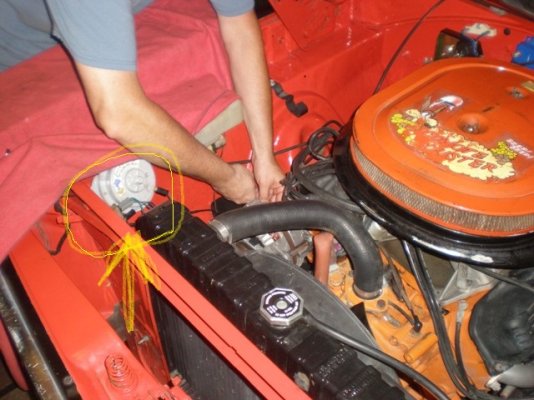
Yes, our cars were born with horn relays. Mounts on the radiator support:
horn reley P6260140.JPG
(As you might expect, there are other threads on FBBO addressing these....)

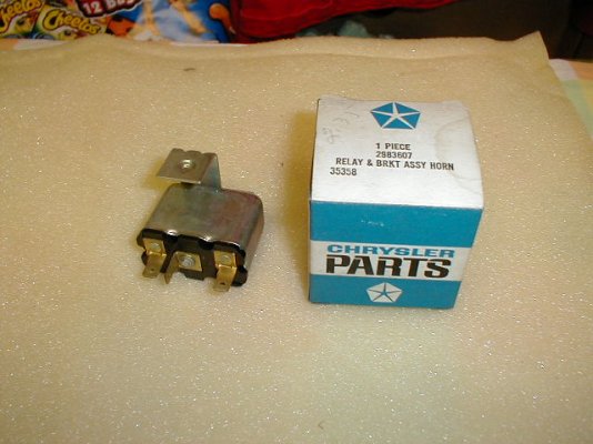
2983607.jpg
The rascals are available all over creation, both NOS and aftermarket. They're parts
store parts really. Don't cost a whole lot.
Some vendors sell a repro wiring harness for 'em too.

From the FACTORY SERVICE MANUAL:
horn.jpg

(As has correctly already been posted by others, "juice" doesn't come to the horn switch/button in the steering wheel -
unless something's wrong elsewhere in the simple circuit, that is).
 
"juice" doesn't come to the horn switch/button in the steering wheel -
unless something's wrong elsewhere in the simple circuit, that is
Actually there is 12V at the steering wheel horn contacts all the time.
Until you press the horn and pull in the relay then it will drop to 0V but you have whatever current the coil requires going through the horn contacts in the wheel.

On a 66 the horn relay is on the firewall.
 
Agreed with moparedtn... the horn switch being a ground trigger for the relay won't get any kind of load. The load is running throught the relay. The ground for the horns itself is via their own chassis. This adds more simplicity on the wiring.

The relay is tipically mounted close or into the fuse block OR like some other models at radiator core support close to the alt. NOTE, IS CLOSE TO THE ALT AND NOT TO THE BATT, as must be correctly sourced every regular accesory, on alt side and not to the batt side. These two locations are close to main positive sources ( fuse box and alt post ) adding EVEN MORE simplicity to the wiring, being a short wire paths to feed the relay from the power source
Not on a 66 the relay is powered right off the starter relay stud which connects right to the battery.
The horn is only on for a couple seconds if at all (in my case almost never).
Again since it's only on for a matter of seconds there is no reason to run a heavy gauge wire to it.

I don't see how location of the relay matters.
The current is the same throughout the length of wire from the power source to the horn.
 
Makes you wonder why they correctly used a relay for the horn thats only on for a few seconds at a time, but did not use relays for the headlights that can be on for hours at a time.
 
Not on a 66 the relay is powered right off the starter relay stud which connects right to the battery.
The horn is only on for a couple seconds if at all (in my case almost never).
Again since it's only on for a matter of seconds there is no reason to run a heavy gauge wire to it.

Hence I said tipically.

I don't see how location of the relay matters.
The current is the same throughout the length of wire from the power source to the horn.
But the amm won't read it correctly hooking it up on batt side.
 
Makes you wonder why they correctly used a relay for the horn thats only on for a few seconds at a time, but did not use relays for the headlights that can be on for hours at a time.
That's why I said, the main reason for the relay is get the horns triggered via ground switch instead positive. The relay makes that job.
 
As a helicopter, turbine engine, helicopter transmission mechanic for 23 yrs along w multiple car, motorcycle, boat and diesel truck builds over the yrs, I'll address some of the queries of @RemCharger.
HEI: Some people would like a hotter spark for a modified engine. HEI is a good way to do it and keep it hidden allowing the engine to appear stock. Some people like a MSD box bolted in the engine compartment.

Manifold vacuum: can be very helpful in an aggressively cam'd engine w an automatic transmission. It does have it's place, however on a stock engine, not necessary.

Quadrajets: Personal preference on type of intake improvement. I doubt very seriously that anyone actually thinks the stock engine in "any" make/model of car was the best performing.

No amp gauge: Necessary... no. Does it have a place, yes for some. I run fuel injection and require a better alternator. I run a 120 amp, I do not want a 120 amp alternator running "through" my dash wiring. I converted to a volt meter that uses the amp guage to show my charging state. And run my alternator directly to my battery.

Headlight relay: Older cars, pre 70's have horrible headlights. Not because the headlights are bad but because the voltage goes through the Headlight switch and then to the headlights. They do not get full 12 volts, much less 14. A relay, activated by the switch allows stock headlights to get over 12V and makes them much brighter "Safer".

I inherited my Great Grandmother's car, I modified it as that's what I like. I honestly don't understand some people liking pro sports, but that's their thing.

For our cars, there are better things that can be added over the yrs to make them more enjoyable to drive. Overdrive, disc brakes, fuel injection, a/c, even tires etc....

I'd venture to bet that the majority on this site modified their car in one way or another.
Thanks for taking the time to make the reply
 
Makes you wonder why they correctly used a relay for the horn thats only on for a few seconds at a time, but did not use relays for the headlights that can be on for hours at a time.
Probably because the return path for the current is through a 'scraping contact' (ring and spring-loaded wheel inside column) instead of a contact or switch closure like the headlight circuits.

Fortunately with the horn relay, the only current passing through the steering wheel ring, is the return to ground current required to energise the relay coil itself....which is miniscule by comparison to the horn current requirements.

PS....I'm sure that Bob Renton would agree with me. :)
 
Been a few years since I owned a Mopar, couldn't remember if it had a horn relay...
That is also a car problem. Been guilty of it a few myself but that's how crap gets started. I find it best to admit defeat if in doubt before posting. I don't remember exactly, but I think it's this way.
 
Actually there is 12V at the steering wheel horn contacts all the time.
Until you press the horn and pull in the relay then it will drop to 0V but you have whatever current the coil requires going through the horn contacts in the wheel.

On a 66 the horn relay is on the firewall.
Don, I pasted the actual FSM explanation of the circuit in my post above (1969 FSM).
The wiring diagram confirms it further - juice goes from the starter circuit directly to the relay.
The black w/tracer wire goes from the wheel to the "G" ground post on the relay.
 
Don, I pasted the actual FSM explanation of the circuit in my post above (1969 FSM).
The wiring diagram confirms it further - juice goes from the starter circuit directly to the relay.
The black w/tracer wire goes from the wheel to the "G" ground post on the relay.
Yes the horn button on the wheel does not power the horn.
But the relay coil for the horn has power anytime a battery is in the car. Since it is a coil of wire and the ground terminal goes to one side of the horn button in the wheel what I wrote is correct.
 
Yes the horn button on the wheel does not power the horn.
But the relay coil for the horn has power anytime a battery is in the car. Since it is a coil of wire and the ground terminal goes to one side of the horn button in the wheel what I wrote is correct.
Do you agree with the folks who designed and made the damn thing or not?
 
Sure it works fine and I don't have a suggested improvement on the design.

But it can be a source of parasitic draw if your horn itself is bad or the wire falls off and your horn button makes contact without pressing the button.
 
There are a lot of horn problems posted throughout the internet with these mopars. Would this simple circuit work, and if so, would I run 10 or 12 gauge wire to be safe and eliminate the relay altogether?

This is a 1 minute video on youtube that includes a simple circuit diagram with no relay; wanting to know if anyone has done this.

The mopar horn relay setup is as simple as it gets. Not sure why you would want to change it. Now if we are talking about the headlight wiring.... that's another story!
 
Auto Transport Service
Back
Top