• When you click on links to various merchants on this site and make a purchase, this can result in this site earning a commission. Affiliate programs and affiliations include, but are not limited to, the eBay Partner Network.

Ign Acc wire heats up in run position. lose "constant" voltage

RoadWarrior

Well-Known Member
Local time
2:49 AM
Joined
Nov 15, 2011
Messages
87
Reaction score
18
Location
Santa Cruz
well, After installing my "universal" harness, I have everything working except in "run" position. Not trying to crank yet.

Now, I've wired everything up according to wire diagram. Problem is different sources say different things. I've been around about 20 different boards and I get different answers. Here's what I got.

From Alternator Battery post I have wire going to fuse box, then from fuse box going to Battery post on starter relay. This feeds things that need constant power like hazards, ignition switch power. I have another wire from Battery post on starter relay to battery. Then from Battery to starter Battery post. First lets verify this is correct because:

I've had people say run another wire from Battery post of alternator to battery post on starter relay. Others have said run from alternator to starter battery post, or straight to battery. 3 different options, all involve 2 wires at battery post of alternator. Usually associated with high output alternators which I dont have. I've always had one wire from alternator to inside feeding accessories with constant voltage then out to starter relay like the stock diagram shows. Is this different due to new harness? more efficient? Thoughts?

my main proof of an issue: hot wires. now with ign 1 feed wire unplugged from ign switch, I have constant 12 volts from battery at fuse box. I have 12 volts coming from ign 1 on switch. But when I connect my ign 1 wire to ign switch then this happens: In run position "feeds voltage from Ign 1 to ballast/ acc feeds 12 volts to fuse box" the voltage from battery/ alternator drop to 6 at fuse box. Acc wire gets hot. This tells me the problem is ballast resistor, voltage regulator, or alternator. I removed ign 1 wire from ballast resistor but nothing. same problem. So maybe voltage regulator?

ign1 splices to ign on voltage regulator, field on alternator, and ballast resistor. I should mention I have electronic ignition so the ecu blue/yellow also splices in to all this. voltage regulator is new, and grounded. Ecu is grounded.

My car started having issues in "run" position before new harness install. So maybe my ecu went bad?

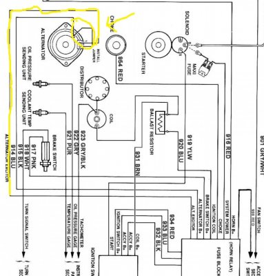
Alt exciter wire from fuse box is not used, but I will mention all new harness diagrams show it replacing ignition one to voltage regulator. meaning ign 1 and ecu are the only wires connecting to ballast resistor. But i've tried both ways and have the same problem.

I think my ignition switch is fine because like I said, as long as my ign 1 feed to ballast resister is removed, acc wire doesnt get hot, I have 12 volts at fuse box, and my lights and everything work.

I am guessing either my ecu went bad finally, or I bought a defective voltage regulator. my third guess is ignition switch, but doubtful.

any suggestions would be great. how to test ecu, regulator, etc. I feel like I am missing something simple since I've wired it correct to mopar diagram with ecu. only difference in this case is a universal harness instead of factory correct.
 
Hello. I'll just come on here and help myself. Maybe I am asking what is considered "newbie" questions?

Anyhow got my old starter relay and it fired up. My brand new relay was bad. Ok problem solved? Still lose Acc voltage to fuse box in run, but have it in Acc. also if I disconnect Ign#1 from ignition switch then put key in run I have my 12 volts to Acc. I removed things one by one, starting with ballast resistor. Nope. Voltage reg. Nope. still no voltage in run position. I only get it by removing wire from ignition #1

There is still the unattached "alt exciter" and "alt power". I am pretty sure exciter is not needed with my ign#1 going to field (maybe this is why I lose voltage in run?) And running "alt power" line from the fuse box to alternator? Seems excessive, but maybe needed with this particular harness? Maybe alt means "alternative power"?

I am still trying different methods with this sweet universal " more like GM" harness. Maybe my real solution is buying a 67 Nova haha.

At least it runs now, and the Acc wire isn't getting hot anymore. Just nee to find out where my ACC voltage is going to in run position.
 
You get different answers because there's more than one way to skin a cat but if not running an ammeter (and I wouldn't) I would run the battery cable to the starter stud then come off of it with the fuse box feed and alternator. If using a voltmeter instead of an ammeter then you can come off of the alternator stud for the fuse feed as well. Take into consideration how many amp alt your running when sizing the wire because after starting that wire will be carrying the full amp output of the alt while recharging the battery which is why it should be a heavy gauge and routed directly to the battery or starter stud. Are you sure you have a battery supplied 12 V to the Batt terminal of the ignition switch?
 
You get different answers because there's more than one way to skin a cat but if not running an ammeter (and I wouldn't) I would run the battery cable to the starter stud then come off of it with the fuse box feed and alternator. If using a voltmeter instead of an ammeter then you can come off of the alternator stud for the fuse feed as well. Take into consideration how many amp alt your running when sizing the wire because after starting that wire will be carrying the full amp output of the alt while recharging the battery which is why it should be a heavy gauge and routed directly to the battery or starter stud. Are you sure you have a battery supplied 12 V to the Batt terminal of the ignition switch?


Thanks for responding!!

Yes, I have 12v to Battery terminal of ignition switch. in my test i left my multimeter connected to constant voltage and my dash voltmeter (I am not running ammeter) connected to ACC at fuse box. I turn key left to Acc only and i maintain 12 at constant battery (feeding battery on ignition switch) and my voltmeter reads 12 as well. Turn key to run (not starting) Constant battery voltage on multimeter drops to about 6 volts, and the voltmeter on my dash barely moves (stays under 8 volts, lowest reading on gauge)

NOW, if I remove Ignition #1 (run) wire from ignition switch, I am left with battery and ACC. (not worried about start and IGN#2 those are fine) turn key to run I maintain my 12 volts from battery on multimeter and also have 12 volts reading on voltmeter on dash. Is it normal for voltage to drop to 6 if I am also sending voltage to ballast resister? The only reason it boggles my mind is my voltmeter always read 12 volts in run with engine off.

so my voltage problem goes away when I disconnect ign#1. There must be a problem somewhere on ignition side around the ballast, voltage regulator, alternator. I've been poking around, removed ballast and put in jumper, etc. no dice yet.


now before, the ign switch, light switch, these were spliced directly to ammeter feed (no fuse)on the stock harness. everything runs through a fuse now (including ign switch) is this causing problems? can't see how. they still get constant feed.

fyi using 10 gauge for all feeds to battery stud on relay. starter has its own feed directly from battery. I followed the directions for removing ammeter, and it said that the starter relay battery lug is a good junction point for battery, alternator, and inside power feed. I just left starter its own feed because that's how I've done it for decades.
 
Sounds like you may be dead shorting the ignition feed, that will cause a voltage drop along with some heat and shouldn't read a voltage drop until the other side of the ballast not the side being fed. A diagram of how you have it wired would be very helpful for us to help too. The starter relay stud is fine but a 10 gauge wire at the alt sounds dicey?
 
X2...diagrams really help us understand how your system is wired up and where any mistakes may be. I've been in the wiring game for 30 years now and it's always so difficult to troubleshoot without diagrams.
 
Sounds like you may be dead shorting the ignition feed, that will cause a voltage drop along with some heat and shouldn't read a voltage drop until the other side of the ballast not the side being fed. A diagram of how you have it wired would be very helpful for us to help too. The starter relay stud is fine but a 10 gauge wire at the alt sounds dicey?

Right on guys. I'll draw it up today. Have it all memorized at this point. I only mentioned having a 10 gauge from alternator because instructions mention a bypass wire for 65 amps and up alternator. I have a 60. Thought maybe that was my issue but with or without it I am still shorting out somewhere. Stay tuned for my art skills!
 
Mr Warrior

The "start/run" system on your car is not by any means complicated according to the wiring diagram for your vehicle so I think instead of a dead short, you are either back-feeding or overloading your circuit some where. A dead short either blows a fuse or torches your wiring very quickly. Providing that you have not made any radical changes to the original equipment ( alt, starter, ignition switch, resistor etc.) you should not have such issues. I'd start by getting rid of the ballast resistor and purchase a coil from MSD or Pertronics that does not require this apparratus - resistors are so "yesterday's news". You can in fact "hot wire" the entire ignition system, bypassing what you've done so far to eliminate the causes - it takes so few wires to do this. Put a temporary fuse in the ignition wire as well to see if you blow the fuse. This will in fact verify a dead short, backfeed, or overload. If the alt requires an exciter and you don't have one you will either be putting out no amps or running full out with amperage. What are the requirements for connecting the alt? In any case keep a fire extinguisher handy and make your battery quick disconnect.
 
X2...diagrams really help us understand how your system is wired up and where any mistakes may be. I've been in the wiring game for 30 years now and it's always so difficult to troubleshoot without diagrams.


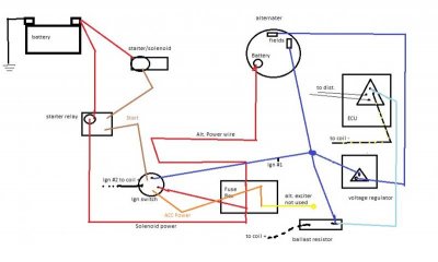
diagram.jpg

here it is. tried to keep it simple. The poorly put together instructions say to use the alt. exciter wire for hook up to alternator field and voltage regulator. Meaning either Ign #1 also splices into this, or ign#1 goes straight to ballast with a splice only from ecu. It's not made clear to me but perhaps my issue is associated with this.

- - - Updated - - -

Mr Warrior

The "start/run" system on your car is not by any means complicated according to the wiring diagram for your vehicle so I think instead of a dead short, you are either back-feeding or overloading your circuit some where. A dead short either blows a fuse or torches your wiring very quickly. Providing that you have not made any radical changes to the original equipment ( alt, starter, ignition switch, resistor etc.) you should not have such issues. I'd start by getting rid of the ballast resistor and purchase a coil from MSD or Pertronics that does not require this apparratus - resistors are so "yesterday's news". You can in fact "hot wire" the entire ignition system, bypassing what you've done so far to eliminate the causes - it takes so few wires to do this. Put a temporary fuse in the ignition wire as well to see if you blow the fuse. This will in fact verify a dead short, backfeed, or overload. If the alt requires an exciter and you don't have one you will either be putting out no amps or running full out with amperage. What are the requirements for connecting the alt? In any case keep a fire extinguisher handy and make your battery quick disconnect.


I have sent ign through 30amp fuse. It blew immediately with key turned to Run (engine off) I tried with alt. exciter and without. There must be a combo I missed. my ACC feed from ign switch goes into fuse box and the alt. excitor is on this feed meaning it only works in run (or acc on switch) but if my ign #1 is feeding the field and voltage regulator I shouldnt need the alt exciter right? Thats what i've been told on other boards, but I fear this is incorrect.

Now when I blew the fuse, I had it running directly to ballast resistor and was using alt. exciter for field and voltage reg. I removed it and spliced ign 1 back up per stock wire diagram and still blowing fuse. Then I bypassed fuse in block and ran ign 1 straight through but still overloading everything. I bypassed ballast resistor with no luck.
 
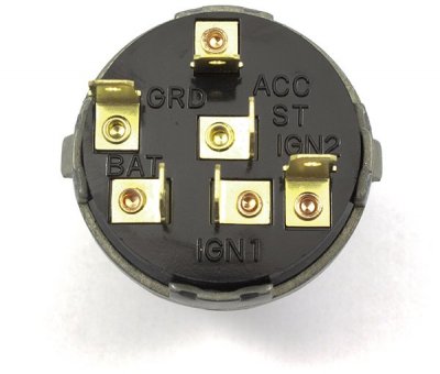
nothing screams out at me on your diagram. It might help to look tag each component's connection points. The ignition switch has 6 contact points I believe and it would be good to verify each wire's connection. Basically like you said, ign#1, Ign#2, ACC, Start, Batt, Gnd

sv1-vg_ignition_switch_back_img_9561_small.jpg
 

well, other than the 5 wire ecu and duel ballast resistor, thats how I have it. I have single ballast with 4 wire ecu. MaybeI just need to rip out ign # feed to everything and re-do it. Maybe I got a bad crimp or wire or something? On stock cars the heavy welded splice from alternator fed everything. I assume the bar on fuse block acts like this welded splice? except everything with constant power is protected now.

- - - Updated - - -

nothing screams out at me on your diagram. It might help to look tag each component's connection points. The ignition switch has 6 contact points I believe and it would be good to verify each wire's connection. Basically like you said, ign#1, Ign#2, ACC, Start, Batt, Gnd

View attachment 314981

I left a few things out as to not confuse.

Battery: power straight from fuse box constant voltage. This bar in fuse box has 2 wires, one to alternator, the other to starter relay battery post. no fuses just constant power to switch.

ACC: wire goes to fuse box and feeds accessories with key on. This is the one that gets hot when key is in "run" (unless I remove Ign#1 from switch. Then ACC power is fine.

Ign ACC: brown wire that from what I see only powers the turn signal flasher and nothing else. I was told to splice this to ACC wire above. (have not done so yet)

Ign #1: as seen on diagram. Goes to splice with alt. field, voltage reg, ecu, ballast resistor. other side of ballast to coil +.

Ign#2: Ballast resistor bypass. Goes straight to other side of resister connected to coil +.

Start: Goes to starter relay.

Ground: told not to use this one.


Really the only wild card is this damn alt. exciter wire. I keep staring at it wondering where it should go because everytime I've tried connecting it problem was the same. But my gut tells me my ign #1 feed handles that issue. it shouldnt matter where the 12 volt feed to voltage regulator comes from right? or MUST it come from ign switch?

At this point I think I'll spend the 15 bucks and get a new switch and see what happens.

I may also try splicing alt exciter wire into one of the field terminals. instructions say I need it, but make no suggestion to whether its shared with ign#1 or replaces it to field.
 
Last edited:
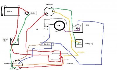
diagram 2.jpg

This is how I imagine it would be wired with Alt exciter. Is is (sort of) how the diagram looks on the poorly drawn diagram that came with harness which I've been told by both other board members and my gut, is wrong. Still uncertain if ign#1 and alt exciter should share a splice or not in this scenario.
 
diagram 3.jpg

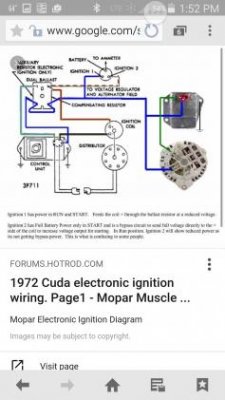
This is a diagram from painless. It shows exciter wire to alternator and ign 1 to ballast. Ign #1 is no longer the exciter like it used to be. But there is no voltage regulator. just a jumper from field to alternator battery post. Self exciting? Now I originally did it this way (except with voltage regulator) and still had same issue.
 
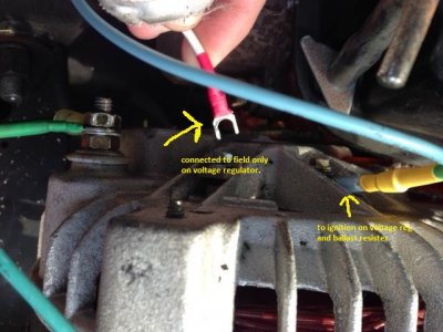
ok, obviously not getting 12 volts to ballast from ign#1. started removing things until finally, I removed the field only jumper from alternator to voltage regulator. I now have 12 volts to ballast resister.


I then suddenly remember a couple times in the past I had these weird drops in voltage (lights would dim while driving, voltmeter dropped to 10) then would randomly brighten up and be fine. The voltage regulator that was on there looked nothing like any mopar regulator I have seen but it was working for the 5 years I had the car. I have a new correct regulator now, but now I know its between these 2.

My guess is my alternator is bad, that or I bought a defective voltage regulator. here is a photo of the field wire I removed to restore full power to ballast resistor.
bad field.JPG

making progress. Still not sure about how (or if) to wire alt exciter wire. I notice everyone seems to ignore that question :)

- - - Updated - - -

anyway to test alternator without engine running? I only know of running tests.
 
Auto Transport Service
Back
Top