• When you click on links to various merchants on this site and make a purchase, this can result in this site earning a commission. Affiliate programs and affiliations include, but are not limited to, the eBay Partner Network.

Need alterator up grade.

Street fighter

Well-Known Member
Local time
1:48 PM
Joined
Aug 5, 2013
Messages
129
Reaction score
11
Location
Vicksburg,Miss.
I have the same problem many early mopars have dim head lights at idle. I want to up grade the alternator to a higher amp so it will idle sitting at a stop light or sign. what is the safe amp to go to with a 73 dodge charger with stock wiring nothing pulling amps but a after market radio, brake lights, heater, and wipers when needed? Don't need any fireworks.
 
I went to a chevy one wire,chrome case,100 amp......100 dollars...regulator inside
 
Smaller pulley might help you.
 
I don't really contribute to much for mechanically issues because some are real experts and i am know where near them in knowledge… Id venture to say unless your charging system is not working properly and your battery is bad your headlights should never be dim provided you have headlights that the car calls for. Id think maybe a bad ground could be the problem. You need to load test your charging system. The voltage is important but the amps the alternator puts out under load is the thing. Id also guess that even at idle with a alternator system which unlike a generator will still maintain a charge to the battery with all accesorys on you could see a slightly dimmer headlight or the blower motor running slower but not enough to make a difference.
 
There's a bracket kit that AREngineering sells that allows the easy conversion to a Denso alternator. I did this modification and it worked out awesome. They even sell a plug for it that really cleans everything up. You just throw it in, remove the voltage regulator from the firewall, and a couple wire mods for the sense wire and you are done. I'd also recommend if you haven't done it yet to do the ampmeter bypass mod.

I want to say the Denso alternator isn't a 100 amp alt, I think mine is around the 70 - 80 amp range but just the newer electronics inside eliminate the dimming issue. I think the part number for it is on AREngineering website.
 
I went with the relays for the headlights. Made a huge difference. Takes the load off the light switch. Slant six Dan sold me my kit. Has a lot of information on his site . worth reading. The bypass kit helps a lot. Check out Mad electric.
 
Bought a Ford 3G 130 amp at the auto recyclers for $60 with internal regulator. Run it on my 383 with the same brackets as my old one but had to space it outward 1/4 inch. Puts out 14.2 volts constantly with all electrical equipment turned on and idle at 650 r.p.m. Ran the 8 ga. charge wire directly to battery (+) post. These are off a Taurus V6 and like their 2 spped cooling fans are bitchin'.
 
Start by reading the Mad article even if you do not "do" this mod. It outlines problems these old girls suffer

http://www.madelectrical.com/electricaltech/amp-gauges.shtml

Be aware that putting "Great Big" alternators on these cars WILL likely cause you trouble without upgrading the wiring. "Ma" knew this look up what is called "police / fleet / taxi" wiring which was used on optional 60-65 amp systems. It ran the alternator charging wires through separate grommets in the bulkhead.

Also be aware that "big" is not always the answer. For example, there's a "medium sized" Mopar alternator about 45A that puts out much more power AT MEDIUM SPEED (RPM) than the 60-65 A does at same RPM.

This is a "by the each and every" type alternator.......newer, "Denso" type style units have been designed to eliminate this problem

As^^ above DEFINATELY upgrade your wiring, use relays, and better headlights.
 
I read the Denso alternators are rated to 14,000 RPM, so a 2:1 ratio crank:alternator pulley size works good so the alternator will put out alot of current at low RPM?
I put a 132 Amp on my Charger, but it is really deep, so I relocated it with a custom bracket. The new location, between the thermostat and valve cover, also provides more contact with the belt.
Front bracket is just some 3/8" strap attached to the waterpump, This is the main support, but used button head bolts for better belt clearance. The a tab welded to the valley pan hold down rail just keeps the alternator in alignment. The support bolt is 7/16" by 6" long, with some washers to get the pulley spacing correct. The spacers really just take up space to the threaded part of the bolt where the nut tightens the alternator to the front bracket. The adjuster was just an old chrome one I had laying around, cut down, drilled a new mounting hole and attached to the power steering pump bracket.

alternator.jpg
 
Streetfighter,

Do you want to maintain originality? or just increase capacity? I believe the original alternator would be a "square back" design vs the earlier round back design. The later alternators (1970 and newer) used a 2 brush alternator design, also called an isolated field design. The problems with the square back design was early diode failures, usually the negative diodes, of which there are 3 positive diodes and 3 negative diodes. When a diode fails, the alternator capacity to supply current is severely reduced to half. If a diode fails shorted, the result will be a discharged battery, usually the next day. But an OPEN diode will reduce the alternators output. Remember that the alternator is a 3 phase full wave design, making AC current which is changed to DC by the diodes. B4 switching to one of the other suggested fixes, I would inspect & fix what was originally installed. You MAY just have a bad diode. These are VERY easily replaced...they come pre-mounted to the heat sink, 3 positive diodes and 3 negative diodes. You can easily see which diode may have failed....it usually just disintegrates. Your electrical loads are nominal. Also remember if you increase the alternators output, that additional current MUST go thru the bulkhead connector to the ammeter and all connected loads and the ignition switch and fuse panel. This bulk head connector has been known to fail due to under capacity of the connectors...they will actually melt...then the car stops.
This is just my opinion, of course.
Cheers,
RJ Renton
 
You don't need a larger amp alternator to run stock lamps. You have a charging system problem.
 
Most of the Mopars from the 60's and early 70's did not charge alot at idle. If you were in drive and idling with the headlamps on and the blower motor on high the headlights would dim some and brighten back up when the rpm came up over 1200. Much of that was normal as the older alt just did not chagre enough at idle. You can see all the service manuals have you check the charging system output at 1200 rpm or higher because thats when they will put out their full output. You can check your charging sytem with a good volt/amp meter and make sure its ok. And I agree if you upgrade to a new alt they put out much more at idle then the older ones do. It never hurts to also put the headlites on relays and take out alot of voltage drop and the load on the headlite switch. The old systems worked ok for the times in which they were out but the newer ones have nearly 50 years of technology to be improved and do a better job. Ron
 
Tuff Stuff performance alts charge at idle. Just saying,
 
I got the AREngineering kit, bought the alt. on ebay, but since I decided to go efi, ac, and radio, I got another alt. that is 120 amp and fit that kit perfectly. So now I have a new 60 amp. alt. sitting in a box collecting dust.
 
Bought a Ford 3G 130 amp at the auto recyclers for $60 with internal regulator. Run it on my 383 with the same brackets as my old one but had to space it outward 1/4 inch. Puts out 14.2 volts constantly with all electrical equipment turned on and idle at 650 r.p.m. Ran the 8 ga. charge wire directly to battery (+) post. These are off a Taurus V6 and like their 2 spped cooling fans are bitchin'.

Hey Yatzee, would you happen to have any pictures of your alternator installed? I have to agree with you that the Ford 3G is far superior to the common GM and one-wire alternator upgrades out there. I did a 3G upgrade on my fox body and really would like to put one on my 440 '69 Charger. Are you running a V belt or serpentine pulley on it? If you kept the V then did the mopar pulley fit? Any little details or pictures of your work would be a huge help! Thanks in advanced, bud.

Respectfully,
Andrew
 
Denso pieces have been the best for conversions on all my projects.
 
The last one I did, was on my WO-car. It has none of the stock wiring. My hemi-wagon had one, also....but that was 8 years ago, and the electrical system was changed on it again[new owner]. I would look into post #5 in this thread.
 
I highly also recommend reading the Mad Electric Mopar wiring tech section too,
or call the guy he loves to talk "usually"...LOL

I done a bunch of different ways...
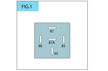
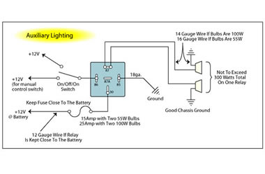
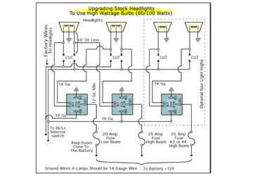
Relays to the headlights is also a great idea,
it shortens the path of resistance &
has constant voltage 12vts at or near the lights

If you really want to cure most all of the ails in the old weak analog system
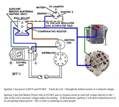
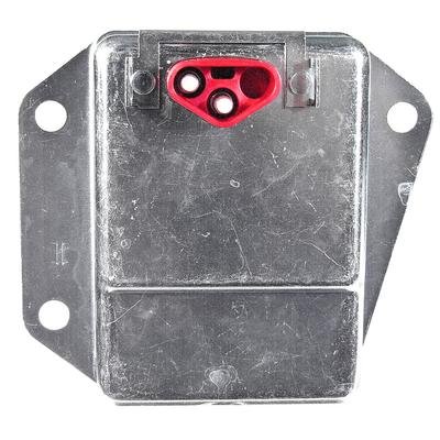
or you could also convert to a newer style electronic regulator too,
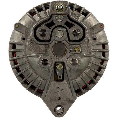
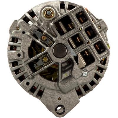
an Chrysler electronic regulator, 4 post ballast resister & 75 amp. alternator
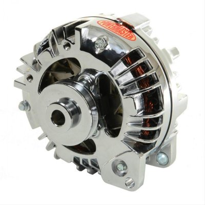
{I used a Chrome cased Powermaster 1759}
to keep somewhat Mopar look or Parts
if your actually worried about that sort of thing

M&H Electrical Fabricators
http://www.wiringharness.com/PDFS/Chrysler_Wiring_Harnesses.pdf
{Sold exclusively by Year One} makes a great plug & play harness
you could also upgrade, if you haven't already
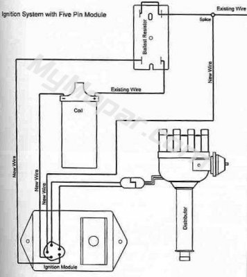
to an electronic ignition, higher amp. alt & an electronic regulator &
still use all OE style/looking Chrysler specific parts,
they have them already done, ready to go...

I've use a 73 & later style Chrysler electronic regulator
a CEI & distributor & a MP CEI Chrome Control Box
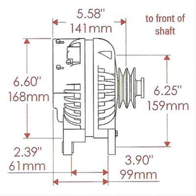
a Powermaster dual feed 75 amp alternator
I also went with a serpentine belt system too...
It works pretty damn good...
Not ideal for racing, but fine for the street...

I've done it a few times on quite a few of my street cars

sort of an easy fix:
But you can also bypass & the shorten the path of resistance that's at the Amp gauge,
You run a 8ga. wire from the 1/4-20 post on the back of the alt. main 12vt output,
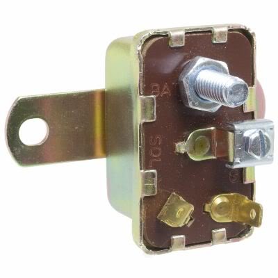
up-to the starter relay that's up by the bulkhead connector,
wire is run along the OE harness along the intake & across the firewall
& it runs up-to the large post, a 1/4-20 terminal on that OE starter relay,
Helps & It will shorten the path {wiring}, helps to be less resistance &
will still maintain the OE wiring too, gauge won't fluctuate *** bad,
it won't bounce &/or discharge at somewhat lower idle speeds either...
It's not a 100% fix, but a great band-aid that actually works...

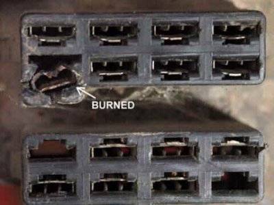
also at the bulkhead connections
{carefully remove plugs &
clean off corrosion & oxidation, add a dab of dielectric grease on all connections,
before you reattach them, also make sure the connections at the Amp meter are solid,
good crimps etc., know to cause melting & fires
},
both areas are big issues in these old Mopars, could be part of your problems...

It could just be bad brushes in your alternator
or a little too low of an idle speed too
or a combo of a bad/weak analog points style reg.,
bad corroded electrical connections or all the above...

what ever you do
make sure all the grounds are tight, adequate size & all connections clean
use dielectric grease on all electronics connections

I always ground the engine to the firewall usually off the back of the intake
add a ground strap to the alt. body, back to the inner fender-well/body too
{again less path of resistance for the old style charging system}
make sure it's a paint free surface/clean, no rust corrosion etc.

There's a bunch of different way you can go,
there are some great suggestions here above too...

good luck
 

Attachments

  • Chrysler Electronic Ignition Wire Diagram 4 pin Ballast & Electronic Volt. Regulator.jpg
    Chrysler Electronic Ignition Wire Diagram 4 pin Ballast & Electronic Volt. Regulator.jpg
    72 KB · Views: 10,667
  • Chrysler Electronic Ignition Wire Diagram 4 Pin Ballast w-5-pin module.jpg
    Chrysler Electronic Ignition Wire Diagram 4 Pin Ballast w-5-pin module.jpg
    60.3 KB · Views: 1,215
  • Chrysler Electronic Voltage Regulator Dual fiels Alt #11.jpg
    Chrysler Electronic Voltage Regulator Dual fiels Alt #11.jpg
    36.1 KB · Views: 345
  • Chrysler Ignition Starter Relay #1.jpg
    Chrysler Ignition Starter Relay #1.jpg
    18.3 KB · Views: 377
  • Powermaster Alt PWM-17519 Chrome #2.jpg
    Powermaster Alt PWM-17519 Chrome #2.jpg
    35 KB · Views: 380
  • Relay #1.jpg
    Relay #1.jpg
    6.5 KB · Views: 306
  • Relay Auxiliary Lighting.jpg
    Relay Auxiliary Lighting.jpg
    14.8 KB · Views: 485
  • Relay For High Wattage Bulbs.jpg
    Relay For High Wattage Bulbs.jpg
    17.9 KB · Views: 399
  • Powermaster Alt PWM-17519 Chrome #1.jpg
    Powermaster Alt PWM-17519 Chrome #1.jpg
    63.4 KB · Views: 360
  • Chrysler Single field Round back Alternator #1.jpg
    Chrysler Single field Round back Alternator #1.jpg
    30.8 KB · Views: 335
  • Chrysler Dual field Square Back Alternator #11.jpg
    Chrysler Dual field Square Back Alternator #11.jpg
    34.8 KB · Views: 542
  • Chrysler Electrical Bulkhead Wiring amp-ga #2.jpg
    Chrysler Electrical Bulkhead Wiring amp-ga #2.jpg
    17.9 KB · Views: 379
Last edited:
Auto Transport Service
Back
Top