• When you click on links to various merchants on this site and make a purchase, this can result in this site earning a commission. Affiliate programs and affiliations include, but are not limited to, the eBay Partner Network.

Sidewinders

Glenwood

Well-Known Member
Local time
9:19 AM
Joined
Jun 19, 2015
Messages
2,929
Reaction score
2,848
Location
Kawartha Lakes, Ontario
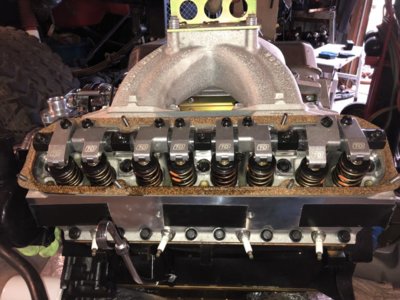
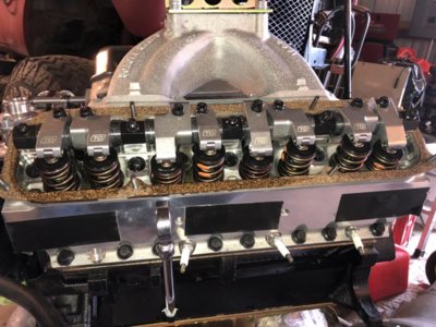
Picked up these sidewinder heads new from T Marsh in NC and paid him to set them up. I sent him the cam specs and spring requirements, but he put different springs on them. He wasn't concerned but I'd like some opinions on this and I have a few questions while setting up the rockers, etc.

Here are the heads.

20180525_164618.jpg
20180525_164555.jpg


cam specs: Lunati 60303
Hydraulic flat tappet
1,800-6,200
Duration at 050 inch Lift:226 int./234 exh.
Advertised Duration:268 int./276 exh.
Valve Lift with Factory Rocker Arm Ratio:0.494 int./0.513 exh.
Lobe Separation (degrees):110

recommended springs Lunati 73100
Dual
Outside Diameter of Outer Spring (in):1.450 in.
Coil Bind Height (in):1.110 in.
Spring Rate (lbs/in):333 lbs./in.
Inside Diameter of Outer Spring (in):1.080 in.
Inside Diameter of Inner Spring (in):0.730 in.
Installed Height (in):1.850 in.
Seat Pressure at Installed Height (lbs):125 lbs.
Open Height (in):1.250 in.
Open Pressure (lbs):325 lbs.

Springs installed: Comp Cams 924
Dual
Outside Diameter of Outer Spring (in):1.509 in.
Coil Bind Height (in):1.175 in.
Spring Rate (lbs/in):347 lbs./in.
Inside Diameter of Outer Spring (in):1.125 in.
Inside Diameter of Inner Spring (in):0.697 in.
Installed Height (in):1.900 in.
Seat Pressure at Installed Height (lbs):112 lbs.
Open Height (in):1.200 in.
Open Pressure (lbs):355 lbs.

retainers are comp cams 741
locks 611 10deg.


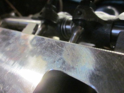
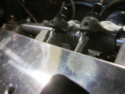
Here is the scrub pattern of these crane ductiles. It looks a little off center to me. Do I have to shim the shaft to move the pattern forward.

IMG_5190.JPG
IMG_5188.JPG

How does the geometry look?
full lift
IMG_5186.JPG
IMG_5180.JPG

50% lift
IMG_5176.JPG
 
Last edited:
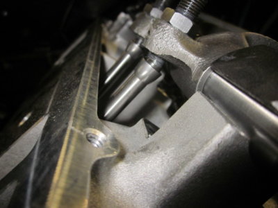
some more pics. Also, the hughes hold downs seem wide and push the intake rockers off center a bit. Will these need to be shaved to center them better? The rockers have a wide pad so I'm not sure if that is necessary. It also seems to cause the 5/16 push rods to the outer edge of the intake bores with slight rubbing. I had to trim (.075) the short bolts as they are a tad too long.

IMG_5178.JPG IMG_5175.JPG
base
IMG_5174.JPG IMG_5173.JPG
 
Last edited:
I will be watching this thread for some of the valve gear experts to chime in.

On the Hughes hold-downs, do they fit snug on the bolts or is there some play left/right in them? I have always ground/shimmed my rocker to get as close to straight on over the valve & I your 5/16" pushrods a scraping the heads, I'd say yes, grind of those hold-downs. You might also want to slightly clearance where they're hitting.

I'm very interested to see the advice others give for your rocker/valve tip contact area vs. shims. They do look slightly off-center & I can see the (intake?) is off to the side as well.
 
i think the 924's will be fine. you might try a .015" shim under the shafts. those non-roller rockers have big scrub patterns. I think the push rods are too short, but you might be ok. it would have been nice to check the rocker shaft oil feed passage for obstructions and flow before assembly; maybe Marsh did this?
 
I will be watching this thread for some of the valve gear experts to chime in.

On the Hughes hold-downs, do they fit snug on the bolts or is there some play left/right in them? I have always ground/shimmed my rocker to get as close to straight on over the valve & I your 5/16" pushrods a scraping the heads, I'd say yes, grind of those hold-downs. You might also want to slightly clearance where they're hitting.

I'm very interested to see the advice others give for your rocker/valve tip contact area vs. shims. They do look slightly off-center & I can see the (intake?) is off to the side as well.


The holes are enlarged so there is some play, but the 2nd and 4th wide ones seem too wide and push the rockers off center a bit.
 
i think the 924's will be fine. you might try a .015" shim under the shafts. those non-roller rockers have big scrub patterns. I think the push rods are too short, but you might be ok. it would have been nice to check the rocker shaft oil feed passage for obstructions and flow before assembly; maybe Marsh did this?


I didn't ask him about oil passages, but he said he went through them and they were ready to run after he set the spring heights, etc.
Why do you think the pushrods are too short? I measured with no threads sticking out, but kind of hard to see in the pic with assembly lube on them. Pics are at base, about 50% and full lift for reference.
 
I was told with the Iron Ductiles that you want to see between 1 and 2 threads out the bottom for proper geometry. You can almost see the 1st thread so I'm sure you will be fine.
 
I was told with the Iron Ductiles that you want to see between 1 and 2 threads out the bottom for proper geometry. You can almost see the 1st thread so I'm sure you will be fine.


I've read many posts from Lewtot mentioning the adjuster threads on irons. He says that the new adjusters are longer than they were decades ago, so measuring with a few threads proud of the rockers throws the geometry off. I can't comment as this is new to me, but I measured without threads showing. When I installed the head, I snugged up the adjuster until the new pushrod couldn't turn and added 1/2 turn (0.020 approx) for preload and took a few pics at different points on the lobe to see the angle of the cup to adjuster.
I'm not sure if the lifters sitting for 6 months will increase with oil pressure, or by how much.

so adding shims moves the scrub pattern forward? How does that translate to the adjuster & pr angle and length?
 
100_0375.jpg
the top adjuster is the old 273/318/slant 6 adjuster; obsolete for decades. the second down is the wedge/gen II type hemi that came with factory rockers, isky/ and earlier cranes. this is the adjuster that is referred to in the engine manuals. these adjusters haven't been used or sold in maybe 20yrs. the bottom two are the newer long adjuster. i think they've been on the scene since around 2000. notice how the ball is extended about .100". this moves the ball down and is equal to 2 1/2 threads showing. the engine manual states proper adjustment (keep in mind this is late '70's to early '80's info and no long adjusters were available) 1 thread showing is ideal, 2 threads may be ok, 3 threads shaky. now with the newer adjuster your already equal to 2 1/2 threads showing when no threads are showing at all. shim the rocker shafts and things get worse.
 
Last edited:
shim the rocker shafts and things get worse. ??? lewtot-- thanks for the pics
shim the rocker stands has nothing to do with it
OP needs to do a mid lift procedure to see if he has the proper pushrods with the adjusters run way up
he may need those thin shims
those pics show too short pushrods before checking for rocker geometry
OP throw some lash caps on and see if your scrub looks better

on his springs OP needs to calculate the open and closed loads at his installed spring height and installed valve open length
he needs to know how to make this calculation using the spring rate- did you get the data posted yourself OP?
either ought to work just fine if numbers posted are correct
I do not see how you can get nice even numbers with your valve lifts

are cup type adjusters available if so you could use a ball and ball pushrod, Magnum/ AMC lifters and oil theadjusters through the pushrods
back in the day we re-tapped for FORD adjusters and moved the screw
I have a set of ERSON 1.75 rockers (NLA new guys lost the tooling)
I prefer rockers with the hard pad

Good checking and questions OP


I posted the spring manufacturer's ratings. The 924's are installed at 1.900"

I'm a bit foggy on the mid lift procedure and calculations you're referring to, so some more reading ahead. Setting up the springs properly is what I paid extra for however.
 
found this in another post. I think I get it...the rocker at mid lift should be in a fairly straight line. How do you determine mid lift? I'm thinking a dial indicator reading the travel from the retainer?

go through the complete mid lift drill
add lash caps if you need to tilt the rocker up when closed (and shorter pushrods) not likely
If you have to tilt down you have to shim the shafts (and longer pushrods)
also check the angle of the adjusters
they should be in a straight line at half lift
 
shim the rocker shafts and things get worse. ??? lewtot-- thanks for the pics
shim the rocker stands has nothing to do with it
OP needs to do a mid lift procedure to see if he has the proper pushrods with the adjusters run way up
he may need those thin shims
those pics show too short pushrods before checking for rocker geometry
OP throw some lash caps on and see if your scrub looks better

on his springs OP needs to calculate the open and closed loads at his installed spring height and installed valve open length
he needs to know how to make this calculation using the spring rate- did you get the data posted yourself OP?
either ought to work just fine if numbers posted are correct
I do not see how you can get nice even numbers with your valve lifts

are cup type adjusters available if so you could use a ball and ball pushrod, Magnum/ AMC lifters and oil theadjusters through the pushrods
back in the day we re-tapped for FORD adjusters and moved the screw
I have a set of ERSON 1.75 rockers (NLA new guys lost the tooling)
I prefer rockers with the hard pad

Good checking and questions OP
shimming the rocker shafts will move the adjuster ball and rocker tip up. if the push rod was ideal this would effect overall length by the thickness of the shim. in fairness my suggested .015" may not be relevant; it's only a quarter turn, but compounded by the push rod being too short it just adds a little to the problem.
 
found this in another post. I think I get it...the rocker at mid lift should be in a fairly straight line. How do you determine mid lift? I'm thinking a dial indicator reading the travel from the retainer?

go through the complete mid lift drill
add lash caps if you need to tilt the rocker up when closed (and shorter pushrods) not likely
If you have to tilt down you have to shim the shafts (and longer pushrods)
also check the angle of the adjusters
they should be in a straight line at half lift
if you check mid-lift at the retainer you'll have to keep in mind the true rocker ratio. it will be probably be between 1.55 & 1.6. the sidewinders are basically edelbrock copies. I know on the edelbrocks I have shelf push rods wouldn't work. I had to go to a significantly longer push rod and had to shim the shafts .030". best thing is just start mocking stuff up and cycling it thru. down side is hydraulic tappets can't be used because they will collapse during cycling.

comp states the 924's have 112lbs at 1.900"; coil bind is 1.200"; spring rate is 347lbs.
 
Take your time, worth it to get it right. My engine was professionally built and haven’t even stated it yet but I just went over mine yesterday for peace of mind (EDE victor heads) some good advice from these guys.

004FF40C-B2F6-4C58-89C4-041534352093.jpeg 67ECDAF0-24D5-489D-BC7E-1D321519FDFB.jpeg
 
iron rockers if on engine stand is relatively simple
remove an ex rocker on the end
put a soft checking spring or no spring on an intake and an old stem seal with a screw clamp
push the valve down to half open and gently tighten the clamp
remove an ex rocker on the end
put the shaft and one rocker on with two hold down bolts
eyeball the line between the valve tip/ rocker pad and the center of the shaft and tangent to the stem (or parallel to the retainer)
line should be parallel to the plane of the retainer
if not shim it up with some matchbook covers or whatever till it is
then use those shims shown elsewhere or make some out of old beer cans or whatever depending on thickness required
take some pics
another way if the cam is in the engine is to rotate the cam with your adjustable pushrod and see if the rocker goes down angle about the same as seat up angle- it should look "right" post some up half-up and down (full open) pics and some pics like you did of the top of the stem
half lift method will give you the narrowest mark , the closest to correct ratio you are going to get and easiest on the valve train
try with the adjuster up as much as possible (so cup does not hit and you still have some adjustment left- i.e. pushrod as long as possible
give us a picture of the adjuster side down, middle and full lift is the adjuster in line with the pushrod at half/ middle (not much you can do about the pushrod side but as I said we used to re-drill and tap to correct but not necessary with your cam and springs
if aluminum and way off send em back
support vendors that make a rocker for the mopar that is not a bastard from somewhere else
 
no time tonight with the honey-do list at full speed lately, but managed to squeeze in a few minutes to try something.
I swapped the wide hughes shaft hold downs with the oem stamped which are .080 narrower. The intake rockers look more centered now. Unfortunately it didn't help the pushrod bores. Anyone ever try to grind these while on the engine? Stupid question I know, but it's a pain to pull them again..sigh!
I will ask our machinist to trim the hughes pieces down to match.

what long type of tool is used to grind aluminum?

20180611_201949[1].jpg
 
Auto Transport Service
Back
Top