• When you click on links to various merchants on this site and make a purchase, this can result in this site earning a commission. Affiliate programs and affiliations include, but are not limited to, the eBay Partner Network.

Some Math about piston to valve clearances

TN Mopar

Well-Known Member
Local time
11:17 AM
Joined
Dec 8, 2015
Messages
526
Reaction score
551
Location
Cleveland TN
I am hoping some of you will be able to tell me what the largest cam I can go with is
I do have the measurements of my current cam and block

440 Block pistons are Speed Pro L2355 30 over with fly cuts and are .029 in the hole
Current cam is the 509 Purple shaft

When I measured the piston to valve clearance, I got 0.120 clearance without gaskets
I use the metal shim 0.020 gaskets

Auto trans
906 heads lightly shaved
with plans for aluminum heads soon

What is the largest mechanical cam I can go with, without having clearance issues?
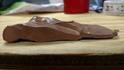
IMG_20190622_171104102.jpg
 
Last edited:
I will give it a shot...but regardless, I still HIGHLY RECOMMEND you re-clay the pistons and check again & be aware that with larger cams other things come into play like "coil bind" on your valve springs. Additionally, I believe duration is more important that lift (in most cases) for piston-to-valve clearance. My calculation attempt is for a "perfect world" where valve gear is perfect & piston valve reliefs are perfectly aligned, etc.

OK, here we go. I will use a Hughes (?) set of recommended clearances of .060" intake & .110" exhaust. The .110" is the larger number, so we'll work with that.
1. Right now you have .120" + .020" = .140" clearance
2. This give you .140"-.110" = .030" clearance left over to play with
3. I will "assume" a rocker arm ratio of 1.5 to 1
4. .030" / 1.5 = .020" to play with on the cam for additional lift
5. .509" + .020" = 0.529" max lift to still keep .110" exhaust valve clearance.

Again....don't just go out and buy a custom-ground .529" lift cam and break some pistons since this calculation is just "theoretical".

I understand that this theoretical and I wont just slap a new cam in
I did want to see the conversation and the math as to how the better engine builders here would figure it out

I don't understand how people get 12 to 1 compression and 600 lift cams in engines without having clearance issues
 
Be careful, valve lift has very little to do with ptv clearance.
 
How are you measuring the PTV clearance?? If you're putting the piston at TDC and measuring the clearance with the valve at max lift, that's WRONG as neither valve is fully open at TDC. This is one reason engines can run huge lift.

You need to measure PTV clearance through the opening and closing cycle of each valve. Even checking them at their max lift point is not sufficient.

As for compression, this is largely due to the piston dome. The domes fill the cylinder head volume to increase compression but they also have valve reliefs so as not to interfere with the valves.
 
I am hoping some of you will be able to tell me what the largest cam I can go with is
I do have the measurements of my current cam and block

440 Block pistons are Speed Pro L2355 30 over with fly cuts and are .029 in the hole
Current cam is the 509 Purple shaft

When I measured the piston to valve clearance, I got 0.120 clearance without gaskets
I use the metal shim 0.020 gaskets

Auto trans
906 heads lightly shaved
with plans for aluminum heads soon

What is the largest mechanical cam I can go with, without having clearance issues?

View attachment 803140

How do you define "largest" mechanical cam?

The is no simple math. Clearance is closest at 8° to 12° BTDC and ATDC at cam overlap, exhaust and intake respectively.

Total lift has nothing to do with PV clearance. It is a combination of duration, lobe rate, and ICL and ECL

IMO, based on my very limited experience with your specific conditions, I would guess that you'd be okay to about the mid 250°s & 0.050"

Those pistons and factory heads were such a common combination, I suspect some will be able to give you a direct answer based on experience.

Finally, usually, cam selection is not based on clearance. It should be based on desired outcome, and if there is a clearance issue, make clearance. It's not that hard.
 
Last edited:
That said, having a fully assembled short block is no time to be checking PTV. You want to do that before putting rings on the pistons, torquing everything, etc.. If fact, checking with a single piston on the crank should tell a pretty good story.
 
How are you measuring the PTV clearance?? If you're putting the piston at TDC and measuring the clearance with the valve at max lift, that's WRONG as neither valve is fully open at TDC. This is one reason engines can run huge lift.

You need to measure PTV clearance through the opening and closing cycle of each valve. Even checking them at their max lift point is not sufficient.

As for compression, this is largely due to the piston dome. The domes fill the cylinder head volume to increase compression but they also have valve reliefs so as not to interfere with the valves.
Everything was measured as I assembled the engine
And as you can see from the picture I used clay on the top of the piston and rotated the engine 3 times by hand
I then took a sharp knife and cut the clay at the center of the fly cut and measured with a dial caliper getting the 0.120

I also think my question was somewhat misunderstood
I wanted to know the math of figuring a larger cam
I am not changing the cam based on this discussion and I certainly would have a long discussion with Hughes before I decided to change it
My intent was to learn more knowledge on selecting a larger cam
As well as not understanding how guys can get such a large cam when I really have so little clearance with the 509
 
You have .140 total so .050 to play with - at the closest point. I’m thinking you could stick in a .590 cam and it would be just fine. You could probably shove in a .650 roller and still be fine.
 
I also think my question was somewhat misunderstood
I wanted to know the math

What part did I misunderstand?

"The is no simple math. Clearance is closest at 8° to 12° BTDC and ATDC at cam overlap, exhaust and intake respectively.
Total lift has nothing to do with PV clearance. It is a combination of duration, lobe rate, and ICL and ECL"
 
As BSB67 stated, there is no real 'math' you can do... there's too many variables; valve timing being the key.. The pros can pick a cam based on judgment from their years of experience. Then they install that cam, degree it accordingly and they check it.... And if there's an issue they set about getting the clearance where they need it. As far as people getting away with much bigger cams, they plan for that high-compression long-duration cam from the beginning and build accordingly..(you did say 'better' builders lol!) Then there's the guys that shove a too-big cam in a stock block because the guys in hot rod magazine did it and...smack!
 
Last edited:
Generally when people talk about "compression" it has nothing to do with the cam. Compression is the ratio of the total cylinder volume versus the volume with the piston at TDC.

Just about every piston has valve reliefs cast or machined into them that will clear most cams. Its when you want to squeeze every last ounce of power out of a motor that it gets tricky. At that point you're choosing the cam and then machining a piston to give you the minimum required PTV clearance.
 
If it is a learning curve you are investigating ?

Rather than simply using clay/putty to measure the Piston to Valve clearance on your current Camshaft, you may wish to employ a Degree Wheel and install light checker V/Springs so you can plot actual Piston to Valve every few degree's of rotation during the Cam overlap/scavenging cycle, as well as the existing Camshafts lobe events in their entirety.
then....
if it is mathematics you wish to employ ?

you can go over here and compare different Lobe Profile events to determine if you have sufficient "room" for a Cam swap.
http://www.compcams.com/Technical/Catalogs/CamLobeMasterCatalog.pdf

We don't care much these days about "static" Compression Ratios, rather people tend to focus more on available pressures in relation to Port velocities/ram effect efficiency and Inlet closing ABDC....
or,
even just a simple "Dynamic" CR calc off inlet closing will do
 
Last edited:
If it is a learning curve you are investigating ?

Rather than simply using clay/putty to measure the Piston to Valve clearance on your current Camshaft, you may wish to employ a Degree Wheel and install light checker V/Springs so you can plot actual Piston to Valve every few degree's of rotation during the Cam overlap/scavenging cycle, as well as the existing Camshafts lobe events in their entirety.
then....
if it is mathematics you wish to employ ?

you can go over here and compare different Lobe Profile events to determine if you have sufficient "room" for a Cam swap.
http://www.compcams.com/Technical/Catalogs/CamLobeMasterCatalog.pdf

We don't care much these days about "static" Compression Ratios, rather people tend to focus more on available pressures in relation to Port velocities/ram effect efficiency and Inlet closing ABDC....
or,
even just a simple "Dynamic" CR calc off inlet closing will do

Right Bob. In fact, if you make some reasonable assumptions about the 509 cam numbers (heck, you probably know the numbers) you could probably look at Comp master lobe catalog and spit-ball pretty close what would probably work.

But I still don't know what "large" means to the OP. There are lobes with about 0.480" valve lift (1.5 ratio) that would probably have too little clearance for his application, and others around 0.580" that would be fine. Which is larger??????

That's why I do NOT discuss Camshafts with people/ internet ? because I just tend to get frustrated and walk away or just plain hang up ! (no patience)
and to tell you the honest truth here...
it's also why when it comes to Camshafts, I have so much respect for guys like yourself or Dwayne over at PRH who CAN and DO take the time & effort to talk/discuss Lobe Profiles with people to best suit their needs ?

I can't do it.... NO time and waaaaay too frustrating explaining until I pass out !
 
The problem is you need to know the cams lobe lift (really the tappet lift) at every point on the cam, and the general cam specs don't give that information. I guess you could estimate the cam profile, but to know for sure you would have to have the cam to measure it unless the cam grinder will provide the detailed information.
Next you need to calculate piston position per degree of crank rotation.
Jeffery Diamonds Victory Library has some good info, and from the cam timing vs compression:
http://victorylibrary.com/tech/cam-c.htm
SE = (S ÷ 2) + R + ((S ÷ 2) × cosA) - SQRT ((R2) - ((S ÷ 2) × sinA)2) <- I think this is the equation to calculate piston position per degree rotation.

With the cam information, you can multiply the lobe lift times rocker ratio to calculate how much the theoretical valve lift is at each point of the cam.

Some other information you need is how much clearance there is from the valves to the piston when the piston is at TDC.
This is easy to check with checking spring on the valves and a dial indicator on the assembled engine, but you could figure it a few other ways too.

The important part is where the cams installed position is in relation to the crank position.
The installed position will increase or decrease the piston the valve clearance, favoring either the exhaust or intake valve clearance.
Usually starting with the theoretical cam centerline "straight up", meaning both valve open the same amount at TDC overlap,
you would run a series of calculations, like in a spread sheet, comparing the valve lift and piston position, at maybe each degree of crank rotation.
This difference between the valve lift and piston position will change until there is a minimum distance.
This is usually around +/- 10 degrees of TDC when the piston is coming up to TDC and reversing direction. Rod ratio plays a part in this given the piston position equation above.
Anyhow, the straight up or split overlap is not where the cam is normally installed, so you could re-calculate at the desired cam installed position, where advancing the cam would reduce intake PV clearance and increase exhaust PV clearance.
 
Last edited:
Honestly, a cam and hyd lifters.......checked with a giant wad of clay like that....... I’d have zero confidence the numbers are right.

As Bob and Russ said....... if you really want to know you need to measure it....... and you need a solid lifter and adjustable “something” to get truly accurate numbers.
 
Right Bob. In fact, if you make some reasonable assumptions about the 509 cam numbers (heck, you probably know the numbers) you could probably look at Comp master lobe catalog and spit-ball pretty close what would probably work.

But I still don't know what "large" means to the OP. There are lobes with about 0.480" valve lift (1.5 ratio) that would probably have too little clearance for his application, and others around 0.580" that would be fine. Which is larger??????

Large meaning more horsepower
But again I was looking for knowledge
Not so much as a cam swap but in the back of my mind I was planning my next engine build
This engine is built and in the car
But I wanted to know how to fit a cam for more horsepower in a zero deck block
all I managed to do was push a few buttons and that was never my intention
 
The problem is you need to know the cams lobe lift (really the tappet lift) at every point on the cam, and the general cam specs don't give that information. I guess you could estimate the cam profile, but to know for sure you would have to have the cam to measure it unless the cam grinder will provide the detailed information.
Next you need to calculate piston position per degree of crank rotation.
Jeffery Diamonds Victory Library has some good info, and from the cam timing vs compression:
http://victorylibrary.com/tech/cam-c.htm
SE = (S ÷ 2) + R + ((S ÷ 2) × cosA) - SQRT ((R2) - ((S ÷ 2) × sinA)2) <- I think this is the equation to calculate piston position per degree rotation.

With the cam information, you can multiply the lobe lift times rocker ratio to calculate how much the theoretical valve lift is at each point of the cam.

Some other information you need is how much clearance there is from the valves to the piston when the piston is at TDC.
This is easy to check with checking spring on the valves and a dial indicator on the assembled engine, but you could figure it a few other ways too.

The important part is where the cams installed position is in relation to the crank position.
The installed position will increase or decrease the piston the valve clearance, favoring either the exhaust or intake valve clearance.
Usually starting with the theoretical cam centerline "straight up", meaning both valve open the same amount at TDC overlap,
you would run a series of calculations, like in a spread sheet, comparing the valve lift and piston position, at maybe each degree of crank rotation.
This difference between the valve lift and piston position will change until there is a minimum distance.
This is usually around +/- 10 degrees of TDC when the piston is coming up to TDC and reversing direction. Rod ratio plays a part in this given the piston position equation above.
Anyhow, the straight up or split overlap is not where the cam is normally installed, so you could re-calculate at the desired cam installed position, where advancing the cam would reduce intake PV clearance and increase exhaust PV clearance.

Thank you 451Mopar
That gave me a lot of material and a good link to follow up on
 
I don't think you pushed anyone's buttons, the replies have been civil enough. As for your next build, I think you'll find - with big blocks - very few pistons with streetable compression are intended to have zero decks. Most will be down in the hole. And if you happen to zero deck the block then you have to compensate with a thicker gasket. Also, most forged pistons will be machined to provide adequate PTV clearance even with moderate lift, solid roller cams.
 
It is a good question, but difficult to answer with precision without having all the cams information.
The calculations are also theoretical and do not account for bearing and valve train clearances, or deflection in the valve train or thermal expansion of parts.
I attempted some calculations a few years ago when replacing the cam in the 500" stroker engine. It originally had a 264/264 @ 0.050" duration can with 112 LSA, and about 0.700+ lift with 1.6:1 rockers. Piston To Valve clearance was OK, but I wanted to go about 10 degrees more duration @ 0.050, and without the cam, the calculations were not at a precision that I could really tell, so I just bought the cam, and installed it, and then checked the piston to valve clearance in the usual way.
 
Auto Transport Service
Back
Top