• When you click on links to various merchants on this site and make a purchase, this can result in this site earning a commission. Affiliate programs and affiliations include, but are not limited to, the eBay Partner Network.

Starter Relay wiring and 4-pin to 2-pin resistor?

Malicious

Well-Known Member
Local time
8:08 PM
Joined
Feb 12, 2012
Messages
786
Reaction score
199
Location
Melbourne
so start with an easy question, 4-pin resistor to 2-pin, can I just join both pins wires from one 'side' to each other and put the 2-pin resistor in its place?

Next one, how do I wire up the starter relay? I'm sure it's obvious but I feel like these two diagrams are showing two different ways of wiring it up:
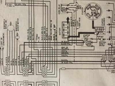
image.jpgimage.jpg

Last one, on the wiper motor loom, two brown wires, they look like they are two ends of the same wire that goes from the bulkhead to wiper motor. Thing is on the loom that came with the car, it had the resistor plugged in there? This plug doesn't appear on any of the wiring diagrams..

Taken me ages to decipher this M&H wiring loom, word of advice, buy the standard engine loom. The modified for electronic regulator and alternator loom doesn't match up to any wiring diagrams. Admittedly this is my first Classic mopar, you vets would probably have this licked in five.

Thanks for the help.
 
Trying to do a bit more research on this and realised my ignition system might play a part in all this.

I have a 4 pin orange box and a 5 pin chrome box.

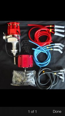
Also brought an electronic ignition kit with a coil, no name just to get me running, that has no instructions. It is an electronic distributor with vac advance and comes with an msd style coil.

So I'm not sure now if I need the ecu or the ballast resistor?

Pic of ignition bits:
image.jpg
 
Last night I worked out its a 'ready-to-run' distributor so I don't need the ecu and ballast resistor. I've unwound the new loom and pulled the ecu wiring out and soldered the resistor wires together, so that's sorted.

I just need some help with the starter relay still, is it;

A.
Bat - to battery
Sol - to starter and 'j' plug via fuse able link
I - to 'T' plug
G - to neutral safety switch

Or

B.
Bat - to battery, 'J' plug with fuseable link and horn relay
Sol - to starter
I - to 'T' plug
G - to neutral dafter switch?

I'm thinking its option B but want to confirm.

Thanks!
 
without really know what you did on the new aftermarket wiring, just can talk about what the stock is and whats the difference between the starter relays. Then you'll need to choose based on what you made.

There are two kind of starter relays used on 70s Mopars, these are the ones using the Ballast Bypass FROM starter relay using the yellow wire signal ( 75 and lates ) and the other one getting the ballast bypass straight from ign switch ( brown wire ) on pre 75s Mopars. The later setup was to save one wire coming from ign switch and of course one cavity on bulkhead. These of course got an extra prong on relay to feed the ballast... not present on earliers relays.

ACTUALLY using MSD ignition modules ( or similar ) you don't need to bypass the ballast, and simply get into the Module tiny red wire tapped into the existant wire runing to + lead of coil. That's because the Modules gets the power source from a constant battery power ( Thick red wire ) and the coil wire is just an ON/OFF signal. You actually can tap them together or not ( eliminating the ballast ), but REALLY not necesary

NOW using systems which doesn't use a diff POWER source, and the ign key signal will be at the same time the POWER source, yes, will need to tap together into one splice, the brown, the blue and the wire to the aftermarket ign system.

If its an earlier Mopar, this wires will be both wires runing to ballast coming from ign switch

If its a later Mopar, will be the one from ign switch and the one coming from starter relay, both of course same as above, running to ballast
 
Thanks Nacho, So I have the earlier style with the brown wire. What I have done, from memory, is solder all the point that would have joined the ballast together, while removing the wires needed for the ECU.

I'm going to run them as per the wiring diagram at the moment, and ignor the 'engine bay diagram' as it seams to make more sense.

The two things I'm still stuck on now are the join on the brown wire to the two speed wiper motor, does a resistor go in there?

And the neutral switch / reverse lights... I'll start a new thread on that.
 
I think you are mixing up lot of things.

both starter relays got the brown traced yellow wire... this comes from the NSS switch

WIPER MOTOR doesn't have ANYTHING TO DO with the ign system. The ballast on 2 speeds motor is JUST for the speed setup, not for ignition, even BY CASUALITY got a brown wire too
 
Auto Transport Service
Back
Top