• When you click on links to various merchants on this site and make a purchase, this can result in this site earning a commission. Affiliate programs and affiliations include, but are not limited to, the eBay Partner Network.

Updating Electronic Ignition on 1969 Roadrunner

darc1722

Well-Known Member
Local time
7:55 PM
Joined
Jan 26, 2011
Messages
212
Reaction score
15
Location
chicago
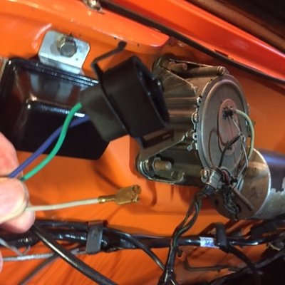
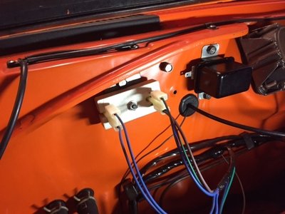
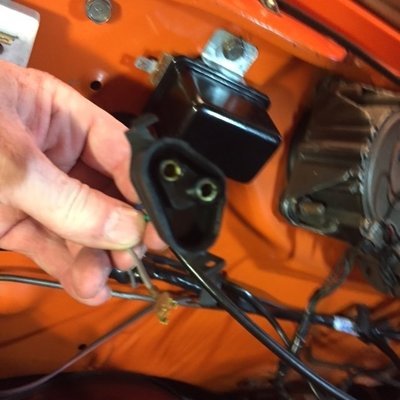
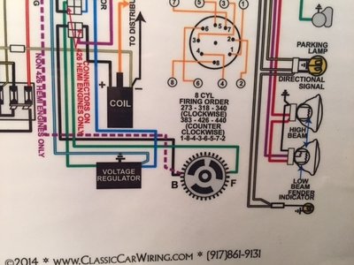
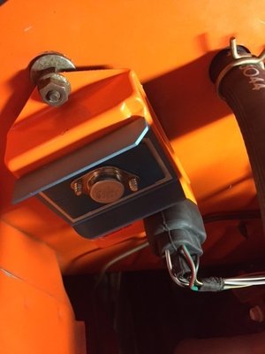
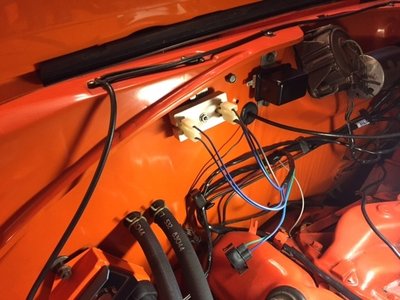
I'm installing a new electronic ignition engine wiring harness in my 69 roadruuner. I would also like to install a new solid state voltage regulator made be Regitar Model:C524 I have a new Mopar ignition module and have everything wired up (i think) but need some input on how and if I can connect the new voltage regulator. The new wiring harness comes with a connector for a different style voltage regulator ( I would like to use the new stock looking solid state regulator if possible). So can I modify the harness to fit the regulator (blue to IGN green to FLD, I think). Do I need the resistor, please see pics and let me know your thoughts thanks. Does anyone have a wiring diagram for what I'm trying to do? Thanks
IMG_2058.JPG IMG_2059.JPG IMG_2050 (1).JPG IMG_2061.JPG IMG_2051 (5).JPG
 
having the wiring and upgrading to elec ign, would make the same on the regulator... the mech regulator is not so efficient like the elect, plus gets electronic noise into the ign system.

of course needs to get the elect reg and "dual field" alt ( new one or become your one into a dual field )

otherwise you can simply cut the reg plug and use it just like was originally installing the terminals ( blue from ign and green to field ), and not use the blue wire field arriving to alt, just the green one. That Blue wire is full 12 volts source from ign, same one arriving to reg.
 
Last edited:
Agree with the above but you can buy a solid state voltage regulator that looks like the older style which I see you have done.
 
Last edited:
can tell about the elect regulator on the old style system efficiency, just can speak about the later elect regulator, which is.
 
If you read the page I posted, it say's.

There are a number of reasons one might want to upgrade a per-1970 system to a transistorized voltage regulator. The list of reason include

  • Chrysler recommends you switch to a transistorized VR if you upgrade to an electronic ignition from a points style ignition.
  • If you have to buy a new voltage regulator, the difference in cost is only about $5-10 more for the transistorized unit. Not to mention, the quality of replacement early style VR's is spotty.
  • The transistorized VR will have a longer life.
Below is a diagram describing how to install a 70 and later Voltage Regulator on a sixties mopar.
But this article was probably written before someone decided they could make a transistorized VR look like the old style to replace the mechanical ones.
 
I din't read the other replies, but they are two different charging systems. Old style regulator (mechanical or electronic) controls the +12 volt ignition power to the alternator field connection, and the other side of the field connection is normally grounded to the alternator so those alternators only have a single connection to the field windings.

The later regulator with the triangular connector regulates the alternator field through the ground side. These alternators have two connections at the alternator for the field winding. The +12 volt ignition powers one side directly (Blue Wire), and the other side (green wire) goes to the regulator and grounds through the regulator case (current controlled by the internal electronics.) The blue wire at the triangular connector provides power to the regulator and it is also how the regulator "senses" the alternator output voltage.

To use the old style regulator, connect the blue wire from the triangle connector to the regulator "IGN" terminal. The Field terminal now needs to connect directly to the alternator field connector. No other connections to this line.
Because your harness is setup for the newer style regulator, it will have a +12 volt ign (Blue) wire at the alternator. Do not connect it to the alternator. Either tape it up or use it to power the electric choke on an aftermarket carb. Just make sure it does not short to ground. Note, it you took the harness apart, you could cut the blue wire from the alternator at the splice and use it on the regulator Field out connection (vs, running a new wire to the alternator from the old style regulator.)
If using an old style, single field connection alternator your done (there is no use for the green wire.)
If using a newer style alternator with the two field connectors, then you could use the green regulator wire to connect the alternator field connection to a ground using the green wire.
 
But this article was probably written before someone decided they could make a transistorized VR look like the old style to replace the mechanical ones.

The deal is the quality of those. I read somewhere somebody having problems with those, so, you can get success being a good quality unit... or not LOL
 
If using an old style, single field connection alternator your done (there is no use for the green wire.)
If using a newer style alternator with the two field connectors, then you could use the green regulator wire to connect the alternator field connection to a ground using the green wire.

I guess you meant blue wire on 1st paragraph

And grounding one of the fields with any piece of wire around on second statement.


ALTHOUGHT having a dual field alt, I simply would get the later elect reg and done, rather than ground one of the alt fields and cut the reg pigtail being the alt and the wiring done for that.
 
Last edited:
anyway, as I told, a roundback single field alt can become into a dual field alt easily... just drill couple of holes on back housing of alt remove the brush attached to chassis and get the isolated brush assembly to install on new holes drilled. Piece of cake
128306-500-0@2x.jpg


I have a good writte up with pics of this procedure step by step, but we are without power at home and its saved at my PC. I uploaded once to Moparts but on an old thread and attachement is lost.
 
Last edited:
Thanks for you input on this got everything wired up but didn't attempt to start last night, because if it didn't start I would not of been able to sleep! Anyway, started this morning on first try! And that's after installing complete under dash new wiring harness as well as new engine harness with electronic ignition updates. Alternator gauge charging fine but Temperature gauge pegged when I started than came back and is bouncing a bit, just replaced this with new style from year one 100.00 WTF Need to figure that out, any ideas, always something!
 
I guess you meant blue wire on 1st paragraph

And grounding one of the fields with any piece of wire around on second statement.


ALTHOUGHT having a dual field alt, I simply would get the later elect reg and done, rather than ground one of the alt fields and cut the reg pigtail being the alt and the wiring done for that.

Sorry, I was making some assumptions here. I think the OP wants to use the old style "looking" regulator that has electronic internals, and that his wiring harness is setup for the newer style regulator. No mention of which type of alternator is being used.
Because of the wiring harness he has, there should currently be three connections at the alternator, the large alternator output, the +12v Ign (blue) wire, and the regulator (green) wire.
My assumption was the OP is going to remove (cut) the new style regulator connector? This would move the blue wire (at the reguator end) to the IGN of the old style regulator, and then the blue wire at the alternator would not be used. To connect the field out of the regulator to the alternator a new wire would be added. This way you don't have to undo the wiring harness wrap. If the OP wants to undo the harness wrap, he could isolate the original blue +12v IGN wire going to the alternator, by cutting it where it splices to the regulator, and then use it as the regulator (old style) field out connection.

I think I know what you mean now... To use the green wire in the harness, connecting it to the old style field out so that no new wire needs to be added? Great idea Nacho.

The gray wire in the photo is for the oil pressure sending unit.
 
Did the gas gauge do the same thing?
The temp gauge doing what you posted makes it sound like the instrument voltage regulator (IVR)?
 
I din't read the other replies, but they are two different charging systems. Old style regulator (mechanical or electronic) controls the +12 volt ignition power to the alternator field connection, and the other side of the field connection is normally grounded to the alternator so those alternators only have a single connection to the field windings.

The later regulator with the triangular connector regulates the alternator field through the ground side. These alternators have two connections at the alternator for the field winding. The +12 volt ignition powers one side directly (Blue Wire), and the other side (green wire) goes to the regulator and grounds through the regulator case (current controlled by the internal electronics.) The blue wire at the triangular connector provides power to the regulator and it is also how the regulator "senses" the alternator output voltage.

To use the old style regulator, connect the blue wire from the triangle connector to the regulator "IGN" terminal. The Field terminal now needs to connect directly to the alternator field connector. No other connections to this line.
Because your harness is setup for the newer style regulator, it will have a +12 volt ign (Blue) wire at the alternator. Do not connect it to the alternator. Either tape it up or use it to power the electric choke on an aftermarket carb. Just make sure it does not short to ground. Note, it you took the harness apart, you could cut the blue wire from the alternator at the splice and use it on the regulator Field out connection (vs, running a new wire to the alternator from the old style regulator.)
If using an old style, single field connection alternator your done (there is no use for the green wire.)
If using a newer style alternator with the two field connectors, then you could use the green regulator wire to connect the alternator field connection to a ground using the green wire.

Thanks for your help on this, it started on the first try after replacing under dash and engine harness plus updated regulator, charging fine but temp gauge bouncing (new style from year one). Any thoughts on the temp gauge, when I first start it goes all the way to right comes back and then bounces?? Always something!!! Thanks and happy fathers day!!
 
Temp gauge was new style that they sell on Year One, that may be an issue. The instrument voltage regulator is on the back of the circuit card correct? Maybe I need to try one of those.......
 
Sorry, I was making some assumptions here. I think the OP wants to use the old style "looking" regulator that has electronic internals, and that his wiring harness is setup for the newer style regulator. No mention of which type of alternator is being used.
Because of the wiring harness he has, there should currently be three connections at the alternator, the large alternator output, the +12v Ign (blue) wire, and the regulator (green) wire.
My assumption was the OP is going to remove (cut) the new style regulator connector? This would move the blue wire (at the reguator end) to the IGN of the old style regulator, and then the blue wire at the alternator would not be used. To connect the field out of the regulator to the alternator a new wire would be added. This way you don't have to undo the wiring harness wrap. If the OP wants to undo the harness wrap, he could isolate the original blue +12v IGN wire going to the alternator, by cutting it where it splices to the regulator, and then use it as the regulator (old style) field out connection.

I think I know what you mean now... To use the green wire in the harness, connecting it to the old style field out so that no new wire needs to be added? Great idea Nacho.

The gray wire in the photo is for the oil pressure sending unit.

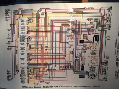
Schematic shows to use Green Wire to the FLD not sure what the Blue wire is for, will tape it up.

IMG_2077.JPG IMG_2078.JPG
 
I think I know what you mean now... To use the green wire in the harness, connecting it to the old style field out so that no new wire needs to be added? Great idea Nacho.
Sure! Just will have an extra blue wire laying around up to the alt which can be used for... whatever... electric choke assitant for example


Schematic shows to use Green Wire to the FLD not sure what the Blue wire is for, will tape it up.

As mentioned, later alts on later elect reg system ( those what use that rubber triangular plug ) use alts with two prongs on isolated brushes assemblies instead just one. These get both fields wired ( + and - ) being positive constant from ign key on blue wires and negative regulated from reg on green wire.

On earlier systems ( the one you car got ) the wired field is just the + which is feeded on the green wire from regulator, while the - field is feeded straight from alt case ( grounded brush ), hence the alt got just one prong and one wire to it.

On both cases the regulated source is green wire just than + on erliers and - on laters.

Just one field is enough to increase or decrease the full magnetic field inside the alt.

Soooo you can cut and isolate the blue wire or simply just leave it around since is already isolated into the existant terminal cover plug.
 
Last edited:
Auto Transport Service
Back
Top