• When you click on links to various merchants on this site and make a purchase, this can result in this site earning a commission. Affiliate programs and affiliations include, but are not limited to, the eBay Partner Network.

Buck voltage converter

Watchthis

Well-Known Member
Local time
6:54 PM
Joined
Apr 5, 2016
Messages
46
Reaction score
27
Location
Ky
Has anyone tried using a buck voltage converter to power the dash gauges? I've seen the solid state regulators that plug directly into the circuit board, but it would seem that a buck converter could do the same thing for $6. Any thoughts?
 
A Buck converter is a FET switch in series with an inductor. There is some sort of feedback loop from the (5V) output to the FET switch to pulse width the voltage into the inductor. A capacitor on the output of the inductor changes the current into voltage. The BiMetal switch in the original dash voltage regulator pulsed DC at a rate such that 5V (average) was across the condenser (capacitor). Enough of the lesson and on to thinking out loud.

I'm stumped on why this DC DC Buck does not function? It is a 3A rating, and I do not believe the cluster requires 3A. Has anyone placed this on the bench with a 15 ohm load (800mA) and then applied 12V to the input to see what the output voltage measures? Then use a 8 ohm load (1.5A) and repeat.

Back in the 1990s I made my own 5V dash regulator. I removed the case of the original regulator and gutted. Bought a LM7805 at Radio Shack and two 10uF, 25V capacitors. Drilled a hole in the case of the old regulator and mounted the LM7805 with a banjo washer with a solder lug. Soldered the capacitors from input to GND and output to GND. Wired back the input and outputs to the regulator pins, and the gauges functioned flawlessly.

Having said all this, the Buck converter in the amazon link should also perform well. You have my curiosity peaked. Please let me know more details!
 
Okay. I just read that this has 'synchronous' rectification. That means that the inductor inside the buck is connected and disconnected out of phase with the voltage switch. I wonder if it would require a larger capacitor than the dash condenser to function properly? Perhaps try this device with a 470uF, 25V capacitor on the output.
 
A Buck converter is a FET switch in series with an inductor. There is some sort of feedback loop from the (5V) output to the FET switch to pulse width the voltage into the inductor. A capacitor on the output of the inductor changes the current into voltage. The BiMetal switch in the original dash voltage regulator pulsed DC at a rate such that 5V (average) was across the condenser (capacitor). Enough of the lesson and on to thinking out loud.

I'm stumped on why this DC DC Buck does not function? It is a 3A rating, and I do not believe the cluster requires 3A. Has anyone placed this on the bench with a 15 ohm load (800mA) and then applied 12V to the input to see what the output voltage measures? Then use a 8 ohm load (1.5A) and repeat.

Back in the 1990s I made my own 5V dash regulator. I removed the case of the original regulator and gutted. Bought a LM7805 at Radio Shack and two 10uF, 25V capacitors. Drilled a hole in the case of the old regulator and mounted the LM7805 with a banjo washer with a solder lug. Soldered the capacitors from input to GND and output to GND. Wired back the input and outputs to the regulator pins, and the gauges functioned flawlessly.

Having said all this, the Buck converter in the amazon link should also perform well. You have my curiosity peaked. Please let me know more details!
The 62 to 65 Mopar Website has how to make a solid state voltage regulator for dash panel.
http://1962to1965mopar.ornocar.org/ml-instrument-voltage-regulator64.html
 
YEP! NTE960 crosses directly to LM7805.

I noticed on the Amazon feedback many people have used the DC DC Buck for USB powered instruments. The specification for MIN capacitance in USB Port power is 470uF. That is why I suggested using a 470uF cap on the output of this DC DC Buck since the condenser is probably very low uF.

So maybe I should try one of these on the 5V output side?
https://www.amazon.com/PCS-ELECTROL...=470+uf+capacitor&refinements=p_85:2470955011
 
Kind of expensive for an experiment. Perhaps see if there are any Radio Shacks left in your area where you can buy a two pack for $2.99. Also see if you have any electrical supply shops that might have these. I suggested 470uF as that is the min value for USB Port power, but in reality a 100, or 220uF might work as well?

I researched that the value of the condenser is probably 0.22uf, which may be too low for the Buck converter.

Here are some examples of low cost capacitor sources:

https://www.digikey.com/product-detail/en/nichicon/UES1E471MHM1TO/493-10832-1-ND/4317806

https://www.tubesandmore.com/products/capacitors

http://www.ebay.com/itm/470uF-Elect...981633?hash=item28224a39c1:g:Kg4AAOSwh2xX~-LQ
 
Are you saying that the original dash cap/condenser would not work with the buck converter?
 
Are you saying that the original dash cap/condenser would not work with the buck converter?
I am 'speculating' that the Buck might need more capacitance on it's output, and the only reason for that suggestion is I read many people were using this Buck for USB powered instruments. USB Port Power specifies a 470uF MIN capacitor.

Having said all this, I would go with a LM7805 and 2 10uF, 50V caps and be done.
 
I tried a capacitor in line with the 5V output today. No luck. Gas gauge comes up slow to E then won't go any farther. Gas gauge is confirmed good and sending unit should be ok as it is only a few years old.
 
I tried a capacitor in line with the 5V output today. No luck. Gas gauge comes up slow to E then won't go any farther. Gas gauge is confirmed good and sending unit should be ok as it is only a few years old.
I assume 'in line' means in series with the output? If so, this is not correct. A capacitor is in parallel with the 5V and GND terminals of the DC Buck output. If you did install correctly, then I'm still stumped as to why this would not work? Can you measure with a DMM and see if 5V is indeed in the circuit?
 
Maybe this is a little clearer as far as what I tried today. The buck converter has 4 wires; 5V output, 5V ground, 12V input, 12V ground.

Buck 5V output to + pin on the capacitor to 5V input on the dash circuit board
Buck 5V side ground to - pin on the capacitor to the ground on the circuit board
12V (IGN) from circuit board into buck 12V input
12V side ground to dash screw
 
Okay, I believe the wiring is correct.

Next test: measure voltage with a DMM from the cluster PCB +5V to vehicle ground like maybe the ash tray. If a solid 5V, repeat measurement to PCB ground. If that's too difficult, then measure voltage from PCB ground (condenser case) to ash tray ground. Should be 0V. If not, then jump the DC buck grounds together. Let me know what you find.
 
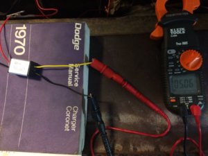
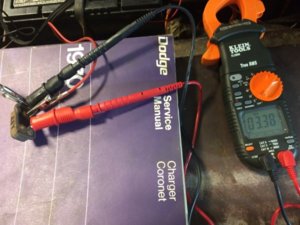
Trying to get back on this. I measured the voltage output of the old regulator and my 5V buck converter today.

The original regulator pinged from 0 to roughly 3V. The maximum was 3.38V. All old-style regulators I have max out around 3.5V.

The buck converter measured a steady 5.06V. Still not sure why it doesn't work for this application.

IMG_6983.JPG IMG_6981.JPG
 
Last edited:
The BiMetal regulator needs some capacitance (and maybe even some load) to sustain 5V. It works similar to your turn signal flasher; if one bulb is out, it flashes slowly. This is due to the lighter load. Try remeasuring the old style with a capacitor, and perhaps a 300 to 500 ohm load resistor.

I agree with you in that the Buck Converter should function properly.
 
Auto Transport Service
Back
Top