• When you click on links to various merchants on this site and make a purchase, this can result in this site earning a commission. Affiliate programs and affiliations include, but are not limited to, the eBay Partner Network.

Degree an installed/unknown camshaft

did you say how you are locating the bottom of the springs?
I use shims from Isky
bvvc with .015 as dampner will chew them up
you can put them under a thicker shim or your locator
 
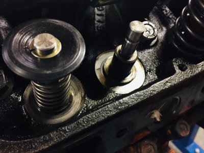
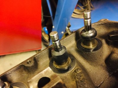
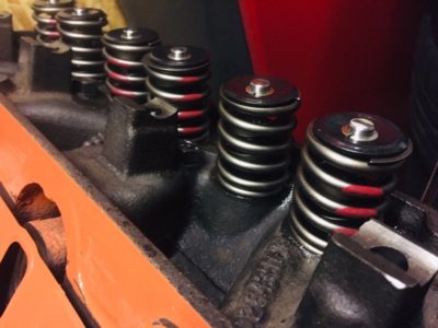
I have a machined locator on the head, see picture.
They were installed before without any shim or locator below.
The diameter of the locator is around 0.990", with the damper ID being 1.008".
I was planning on using these shims in 0.015" and 0.030". https://www.summitracing.com/parts/hrs-96230-15
I ordered a proper valve spring height checker as well to measure them all up first and go with the lowest installed height found.
Those shims are hardened, would they still be destroyed by the damper?

I should have a space of around 0.090" before getting issues with coil bind so adding a 0.030" shim should be no problem height wise.

IMG_3742.jpg
 
I had received the rocker shaft shims and added a 0.040" shim below.
But with using an adjustable push rod i did not see much difference in roller sweep on the valve tip.
I send a mail to B3 and await his instructions on what he needs to know and fabricate the proper correction kit.
Too much playing around, i want to get the engine back in the car.

Just waiting on new valve springs i ordered (should be here Wednesday i hope) together with shims to install all springs with the same height.
Once that is done, waiting on the B3 kit and after installation just need to measure for the correct push rod length and order them as well, then i should be set.
Oh no..new headers also :)

In the mean while i have not been sitting still...
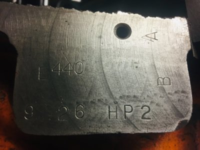
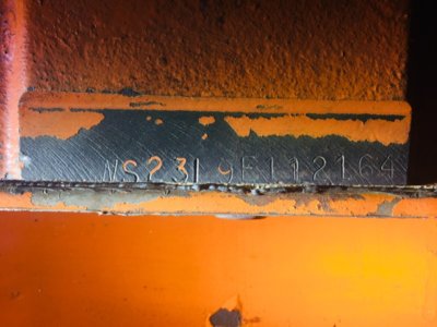
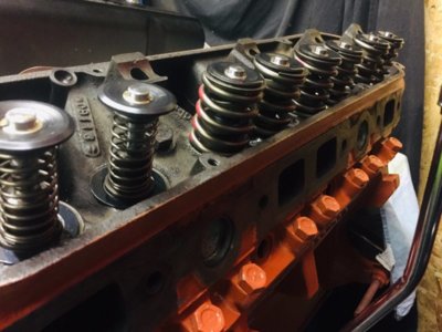
Got some good pictures of the stampings on the block for future reference.
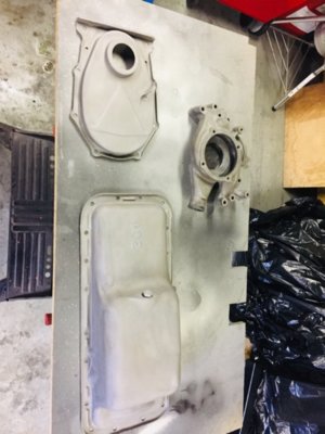
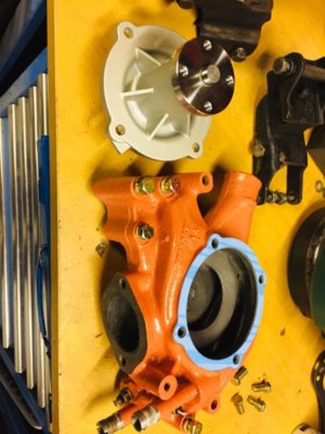
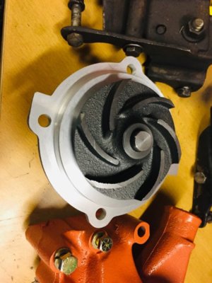
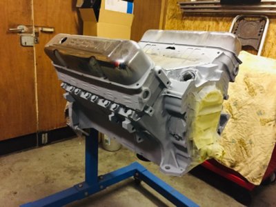
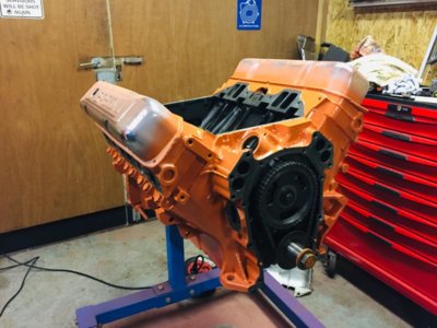
Cleaned and painted the engine, installed heli coils in the worn out threads, got a new 440 source water pump, MP windage tray, new flex plate and fasteners and a new 440 source balancer.
All seals new in place, still waiting on my Melling HV M63 oil pump which comes together with the valve springs.

IMG_3762.jpeg IMG_3772.jpeg IMG_3773.jpeg IMG_3779.jpeg IMG_3787.jpeg IMG_3751.jpeg IMG_3753.jpeg
 
B3 geometry correction kit is under construction, probably will take 2-3 week before i will get it.
Once that is installed still need to check for the correct length of push rods.

I noticed that the current preload on the hydraulic lifters had been set to the bare minimum.
The little piston is just slightly off the retainer ring, i can only mention 2 reasons for that; either has to do with the previous PV clearance (when it was advanced) or they did it to make it behave like a solid tappet for gaining some.
Going by the Hughes website their recommendations on their camshaft a preload of 0.080" - 0.095" is recommended.
Not sure what determines the preferable preload, the lifter or the camshaft?
What is a "safe" minimum preload to run?
At the moment i have around 0.100" PV clearance, so putting 0.095" of preload might be too close right?
Once the B3 kit is installed, and i can start playing with the push rod length i believe i will need to find the sweet spot of how much preload i will be able to run with what pushrod length right?
B3 recommends to go with the longest pushrod possible, as far as i can see it looks like i cannot shorten the adjuster screw on the rocker arm much more due to the oiling hole being quite low.
Currently they stick out around 0.300", maybe i can reduce it to 0.250" but i am not sure if that oiling hole is spraying oil or just dripping?
If it drips i need to make sure the pushrod cup sits below it when the valve is in the closed position.

Also ordered a set of TTI headers, 1-7/8" primary's and C5 finish. ceramic coated and thermal barrier inside.
Still waiting on my damn springs and oil pump....
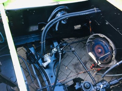
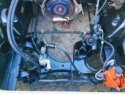
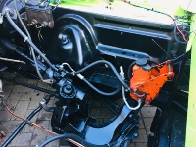
Anyway, had some time spend on cleaning the engine bay and getting it ready for a paint job.
After all this is done, hopefully i have a nice looking engine bay with a 440 that spins like a kitten :)
 
https://www.enginelabs.com/engine-t...mp-cams-new-xd-a-shim-adjustable-ls-pushrods/
see the comment

The easiest way to check the amount of preload is first to put the lifter on its base circle. Place the pushrod and rocker in place and gently tighten the rocker bolt until there is zero free play. Now count the number of turns required to tighten the bolt.

The thread count on the rocker bolt is the metric equivalent to 20 threads-per-inch (TPI). This makes one turn of the bolt move the piston inside the hydraulic lifter 0.050-inch (1/20 = 0.050-inch). Establishing a custom pushrod length that will depress the lifter piston between half of a turn (0.025-inch) and one full turn (0.050-inch) is the ultimate goal.

Previous dyno tests by our colleague Richard Holdener have shown an advantage to increasing the amount of preload in the hydraulic lifter on any engine.
His testing was performed on a 383ci LS engine that uncovered a power gain of 14 horsepower, going from 515 to 529 hp.

That’s impressive and was using COMP’s standard off-the-shelf 0.080-inch wall 5/16-inch-diameter pushrods. While not all engines will experience this same level of improvement, it does reveal the importance of accurately setting the lifter preload.

comments everyone???
 
I came along a lot of info that tells the opposite story, where too much preload causes poor idle, low vacuum and power loss....

Hydraulic lifter preload is the distance the pushrod plunger is depressed below the retaining lock. Preload should be between .020"-.060" for the lifter to perform properly. With too little preload, the valve train will be noisy and the retaining lock may fail (break or pop out) due to excessive hydraulic force against the retainer. Conversely, too great a preload (more than .060") will produce excessive lifter pump-up, causing the valves to open longer and lift higher, drastically reducing cylinder pressure and hurting engine performance. The engine will also have very low vacuum, causing it to idle very poorly.
https://www.laneautomotive.com/PumpItUp.htm

As per Hughes the amount of preload is not important.
http://www.hughesengines.com/TechArticles/12hydrauliclifters.php

I understand their point in saying that, it the would have mentioned directly after this statement that the PV clearance should allow you to run that preload.
If the valve spring does lose control when over revving happens, there will be some interference issues.

I assume that once the valve train is installed in it's final position, the rocker arm adjustment screw needs to be set in such a way that oiling is still happening while keeping it as short as possible.
Then install the adjustable pushrod and set it to a length to take all the slack out.
After that, and by using the checking springs, i need to confirm the PV clearance again and see how much space is left there.
Based on that figure i can select the preload in such a way that even when the lifter would be fully pumped up there would still be no interference between valve and piston. (if it does, the pushrod needs to be shortened)
Once that pushrod length and preload is determined, i can add these figures together and get the total length of pushrod i will require.
(for geometry benefits i want to keep the adjuster screw as short as possible)

Is this correct way of thinking?
 
Current adjusters are ball type.
I know i could gain some by changing them to cup style, then i also will need push rods with ball-ball end and oiling hole.
 
your choice
you can get cup and ball pushrods with the oil hole
or change the adjusters ball and ball pushrods may be cheaper- go strong
BTW you're looking good
I disagree with hughes a lot
even if you are not racing preload makes a difference
you are correct
(for geometry benefits i want to keep the adjuster screw as short as possible)
more strain on the rockers with long adjusted adjusters and they break
also as you say geometry on the pushrod side, while not as important as the valve side, is still important
if adjusters are way off lining up with pushrods near mid lift (notice nothing is prefect wording here) post some pics open, mid, closed
 
I had seen the other topic about that broken rocker arm, there also that adjuster screw was very long indeed.
Sometimes i feel like Hughes knows their stuff, they are just not advertising it or at least not going in all the small details.
Some off their instructions also seem to provide 90% of the information, the rest is the fine details you should know yourself.

On the pics below, you can see with the old setup that the pushrod is closest of being straight at the full lift position. ( straight meaning the adjuster and pushrod being in-line)
But this is probably caused by that it is a roller rocker and the rocker shaft has not been raised up.
With that B3 kit installed the straight position will be coming more to the half lift position i guess.

IMG_3797.jpg IMG_3801.jpg
 
Hey guys,

I have checked all the valve spring installed heights with below numbers, the red numbers behind them should be the final measurement when corrected with a shim. (shim size between brackets)
What you guys think? Acceptable?
Maximum deviation ends up being 0.014".
The Hughes HUG 1106 springs i am going to use recommend an installed height of 1.880", which gives a spring tension of 150 lbs.
At full lift i should end up with around 340 lbs of spring tension.
Max. lift is 0.576", coil bind hits at 0.680" so i have around 0.100" clearance.

Springs:
http://www.hughesengines.com/Index/...Y2sp&level1=VmFsdmUgU3ByaW5ncw==&partid=10270

#1 #2
Ex: 1.912" 1.882" (0.030") Ex: 1.906" 1.891" (0.015")
In: 1.923" 1.893" (0.030") In: 1.907" 1.892" (0.015")

#3 #4
In: 1.897" 1.882" (0.015") In: 1.908" 1.893" (0.015")
Ex: 1.919" 1.889" (0.030") Ex: 1.913" 1.883" (0.030")

#5 #6
Ex: 1.907" 1.892" (0.015") Ex: 1.910" 1.880" (0.030")
In: 1.897" 1.882" (0.015") In: 1.898" 1.883" (0.015")

#7 #8
In: 1.905" 1.890" (0.015") In: 1.906" 1.891" (0.015")
Ex: 1.924" 1.894" (0.030") Ex: 1.908" 1.893" (0.015")


UPS f*cked up somewhere so i still do not have received my springs...
Did manage to get the complete engine bay cleaned, degreased, sanded and painted which looks a lot better then before!!
 
WE may have posted here or on another thread
B3 has a #4 tech tip on pushrod geometry
B3racingengines.com
All good IF your cam vendor wants 150 on the seat and 340 over the nose
 
WE may have posted here or on another thread
B3 has a #4 tech tip on pushrod geometry
B3racingengines.com
All good IF your cam vendor wants 150 on the seat and 340 over the nose

Yes, Hughes recommends these springs to be used with the HE3844BL cam.
The reason asking on the installed height is, i could bring it in even closer but some end up just below the recommended 1.880" and i will have to use 2 shims instead of 1.

For example: Cyl. #7 exhaust valve; if i add another shim of 0.015" it ends up 1.879".
There are several more i can add one, and end up just below 1.880"
Also just realized and checked the measuring tool which shows 0.005" more if i check it with a caliper.
When adding 1 more 0.015" shim on several places i will end up more close to the 1.880", deviation does not change (0.014") but i get to the 150# spring pressure.
The old used spring i had checked was found with 128# with an installed heigth of 1.920".
Could there have been a reason to reduce the seat tension or likely they never bothered checking this?
I think they did not look at the installed heights at all, or they would have corrected it, right?
 
Ok, i got to replace all valve springs and got below installed heights.
Maximum difference is 0.015" between the highest and lowest measurement, recommended installed height is 1.880". (being slightly lower is no problem right?)
New springs, keepers and valve stem seals.
I reinstalled the checking springs on cylinder #1 as i still want to check the PV clearance once i got it al back together.
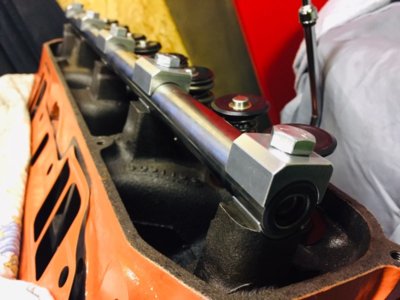
I also received the B3 kit, which looks very fancy, too bad i have go back to work tomorrow so i cannot complete the installation and see how the geometry ends up.
I still have to elongate the bolt holes in the rocker shafts, about 0.075" to get sufficient clearance when installing the kit.
And need to determine the correct push rod length and order them.

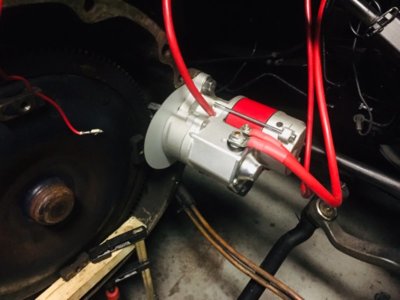
Engine bay is as good to receive the engine, still installing new wiring for new mini starter motor and got a new steering pump ready to go as well to replace this old one.
New TTI headers are on the way as well as some more bits and pieces as new bolts for the motor mounts, someone installed metric bolts which leaves too much slack in the bolt holes and causes the bracket to hit the engine block which i want to avoid.
Anyway, hopefully i will be back again in 5 weeks and continue this story!
Thx for reading!

#1
Ex: 1.878"
In: 1.884"

#2
Ex: 1.888"
In: 1.885"

#3
In: 1.875"
Ex: 1.884"

#4
In: 1.887"
Ex: 1.878"

#5
Ex: 1.885"
In: 1.882"

#6
Ex: 1.874"
In: 1.879"

#7
In: 1.882"
Ex: 1.885"

#8
In:1.887"
Ex: 1.889"

IMG_3875.jpg IMG_3981.jpg IMG_3982.jpg IMG_3865.jpg IMG_3866.jpg IMG_3867.jpg IMG_3983.jpg
 
Last edited:
Everyone should be so lucky
in your case it's not luck but attention to detail
thanks for the update
 
I am really hoping this is going to end in a succesfull result.

I do wonder though, if i find the PV clearance too close, guess i will have no other option to advance the camshaft again i think?
I can use the 4* advance key way on the crank sprocket to do so.
 
don't get ahead of yourself
it would depend on which valve whether you advance or retard
but you should be fine
but check
post some before and after pictures of your b3 kit installation
how much difference did it make
 
Yeah, very true.
Although being severely advanced before my guess is that that is the safe side.
Will see, before i had around 0.100” clearance with the camshaft in it’s current position.
I will take pictures when installing the kit, then we can see some differences between before and after.
 
Hey guys,

Today i have started to do the modification to elongate the bolt holes in the rocker shafts.
I got 1 shaft done so far, it is a job that takes time and patience. (i need to remove 0.075" (2mm) material)
A few test fits in between to avoid removing too much material, but the result should be good.
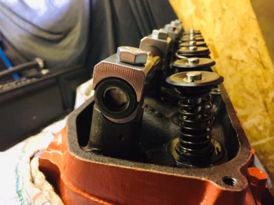
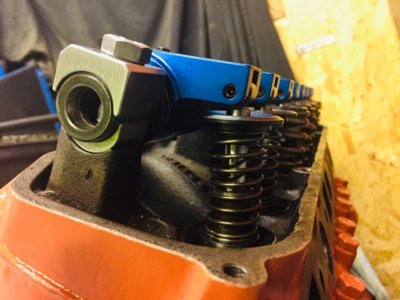
Also had to do the shimming of the rockers once they all fit nicely and got them all with a slight axial clearance of 0.005" - 0,010" between the rocker shaft hold downs.
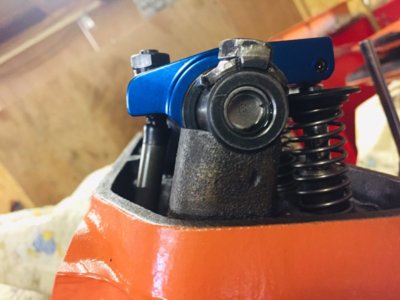
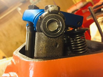
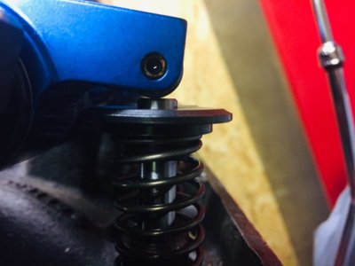
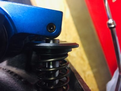
Now as seen on the picture the roller sits slightly towards the intake side of the valve stem.
Later i will check the sweep with an adjustable push rod, and i will have to measure what the push rod length is that i will require.
Let's hope it is a standard size to avoid needing special size...

IMG_4161.jpg IMG_4162.jpg IMG_4163.jpg IMG_4164.jpg IMG_4165.jpg
 
Last edited:
I am sure you have checked it but the roller looks like it could run of the valve stem at max valve opening.
 
Auto Transport Service
Back
Top