• When you click on links to various merchants on this site and make a purchase, this can result in this site earning a commission. Affiliate programs and affiliations include, but are not limited to, the eBay Partner Network.

Fuel gauge on rallye cluster

USatC

Well-Known Member
Local time
1:59 PM
Joined
Mar 20, 2017
Messages
215
Reaction score
5
Location
Montgomery
Dropped my tank last week and noticed my sending unit had no line running from it (that would explain why the gauge doesn’t work). I was wondering if i could directly run a wire from the gauges to the sending unit. I tested the car with the ignition turned to on and i get no voltage out of the blue line. Is that expected?
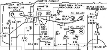
87DDC9FF-54D2-4E92-8B93-9E1B7EBF59B2.jpeg
 
You could run from the gauge to the sender unit. The sender is a variable earth.
You should see power on the blue wire. Do the other gauges have power?
 
I don't honestly know if you should be able to see power to the blue wire. I tested all mine, but I never shecked for power on the negative side of the gauge, or the wire coming from it.

I know power goes to one side of the gauge and the ground connecting to the other side is a variable resistance ground, like Steve said, but I never tried to measure power on that side of the gauge while connected. I know the gauge has a resistive bi-metal strip in it that, depending on downstream resistance, moves a set amount to move the needle. I just don't know if you can accurately measure power on the ground side.
Maybe i’m a little confused about the blue wire. Where should i run a line from my sending unit to the gauges? I don’t see power of either line that feeds the gauge.
 
You need to pull the terminal off and test for power. The test light may be dim because they are reduced voltage around 5 or 6. If you see power put the terminal back on.
Attach an earth temporarily to the earth terminal (the other one) and the gauge should move all the way to full or hot depending on the gauge.
Do not leave the earth on this will damage the gauge unit. Just short it to see if it will move.
This test will assure you the gauge is not faulty.
I’m running a multimeter and i don’t see voltage to either side of the gauge
 
The blue wire comes from the gauge into the harness that runs down the left side kick panel. From there it should run under the left side under the wire protector all the way to the trunk. The wire drops in through the trunk to the under side of the car through a grommet. Then to the sender.Also you will need a ground strap to jump the rubber hose back to the hard line to the sender. Otherwise you wont get a good voltage reference to the gauge.

Check the voltage limiter which is the little silver 3 post box that is in the back side of the gauge cluster. If its not good then you wont have the 5 volt output that the gauge needs.
I’m not seeing voltage to any wire to the voltage limiter.
 
Check your “ACC” fuse for switched power, the limiter is fed from that fuse.
However, the temp and oil pressure gauge are also powered from the limiter, you didn’t mention they were not working as well.
Be careful with that diagram you posted from the FSM, there is an error, does not show the feed to the fuel gauge from the limiter, should have a jumper from the gauge above it.
gauge.jpg
 
Last edited:
These schematics may be a little easier to trace down your wiring on. Be sure to check all fuses. I had no dash lights no turn signals and a few other issues.. Turned out to be a blown fuse that looked like it was in good shape.

71SatelliteGTXRoad RunnerA.JPG
71SatelliteGTXRoadRunnerB.JPG
 
The following is from this link:

http://board.moparts.org/ubbthreads/ubbthreads.php/ubb/showflat/Number/5550004/site_id/1#import

I've reformatted the original Word Fort so it's easier to follow:

OK, bear with me this will be a little long. I assume you have tested all your gauges and they are functioning. If not here's what I did:

I took a standard 3 D-Cell battery flashlight and used it as a power source. 3 D-Cells put out almost 5 volts very nicely. I hooked some jumper wires to the back of one gauge at a time, Positive to the Red in my picture and the negative to the other post which corresponds to the sending unit. If the gauge peg's you know it's working. (I've read you can use a 9 volt battery , just be careful no to fry your gauges!!)

All the other posts where they say to ground the wire at the sending unit will only make the gauge work if it is in fact functional and if the cluster is getting power and your voltage regulator is working. (lots of and's... I had to check everything since that did not work for me).

If all your gauges are working, check the voltage regulator. Again, I have no special tools only a multi tester so here's what I did: I pulled the voltage regulator out and hooked 12 Volts directly to the input (middle post), I then grounded the regulator right to the cars battery (post hanging off the case) and hooked up my multi tester to the 5 Volt output (Bottom post). The meter should bounce around from zero to ~5 volts. If not the regulator is shot. Do a search on this site for how to update it to solid state or get a diffrent one.

Now on to the wires. As in my picture everything is color coded. The 5 pins at the top of the circut board is where the plug from the dash harness hooks up. (This was my problem, the previous owner must of had the dash out at some point and the plug was in upside down!!! None of my gauges worked and neither did the dash lights because the power was all going into the Temp sending unit, I think that's what burned out my temp gauge) So, make sure the Orange wire is on the side closest to the speedo and the Grey wire is on the opposite end. That's all you need to run the fuel, temp, and oil gauges.

Getting the dash lights to work is a whole other post. If everything is hooked up, the cluster is well grounded, and you are getting power..... Then you can check the gauges by grounding out the wire at the sending unit and the gauge should go to full. If not, might be the sending unit.

Testing gauges: A voltage limiter needs to be plugged into the circuit board. Attach a 12v power source to the circuit board pin that supplies power to the board. Ground the cluster housing. Go to Radio Shack and buy these resistors. 271-1101 10 ohm 271-1103 23 ohm 271-1109 150 ohm Just attach a short piece of wire with a small alligator clip on each end to a single 10 ohm and 23 ohm resistor Take two 150 ohm resistors and put them side by side and then attach the wires with clips. The jumper wires are so cheap you could make three of each and have all your gauges testing at the same time.

The LOW position is 73 ohms The MIDDLE position is 23 ohms The HIGH position is 10 ohms Temperature gauge The L position should read 120* on the dial The M position should read 170*~180* on the dial. The H position should read 250* on the dial.

Oil gauge The L position should read 0 psi on the dial. The M position should read about 30 psi on the dial The H position should read 80 psi on the dial.

Fuel gauge The L position should read empty on the dial The M position should read just under 1/2 on the dial The H position should read full on the dial.

All the above are plus or minus about 1/16ths of an inch. Here's how you can check to see if the voltage limiter is working. Voltage limiters can be tested out of the car with a few jumper wires and a test light. Hold the limiter with the terminals facing you. The horizontal terminal should be on the top. The vertical terminal in the middle and the angled one on the bottom Ground the horizontal terminal. Supply 12v to the vertical terminal. Touch a 12v test light to the angled terminal. You should get a pulsating light on the test light. If the light doesn't flash or stays on all the time the limiter is bad. The limiter does not provide 5v. It provides a pulsating 12v that averages out to 5v.​
 
Auto Transport Service
Back
Top