John Folz
Well-Known Member
Just a quick intro before we get into the main subject here. I have been a long-time lurker and read through all the major restoration threads. They have been a huge help and confidence boost to undertake this entire project. I am currently in the process of restoring a 1966 Charger. It was originally a 318 Auto. Drivetrain is long gone so the plan is a basic 440 build that will look as original as possible. There is not a restoration thread as of yet because work has been sporadic due to time and money constraints. Car has had all the major metal work done IE: Floor pans, Trunk pan, and inner fender aprons. All done at home. I have been slowly redoing all the original parts that I can and building a collection to assist with assembly once the body gets painted.
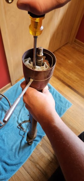
So that brings us to this weekend’s project. The steering column. I browsed many threads on column rebuilds but did not find one specific to 1966. Which is different than the later collapsible years. The column was very intimidating at first but was definitely a lot easier than expected. I tried to photograph and document as much as possible. Hopefully this thread helps others with any questions and if there is someone who sees something I miss please correct me!
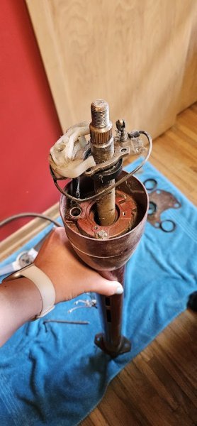
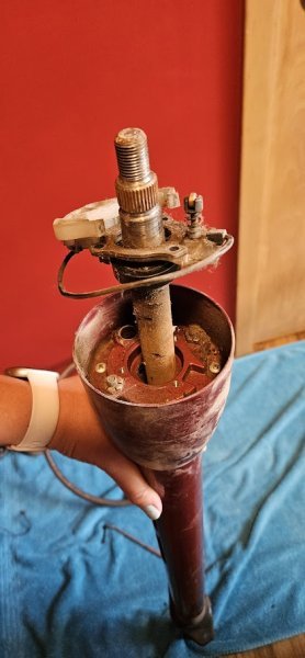
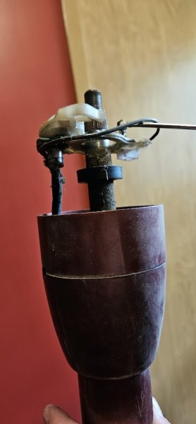
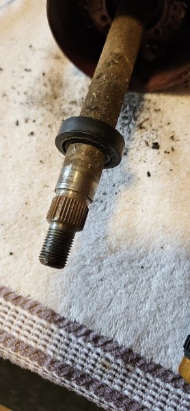
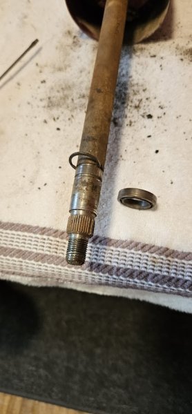
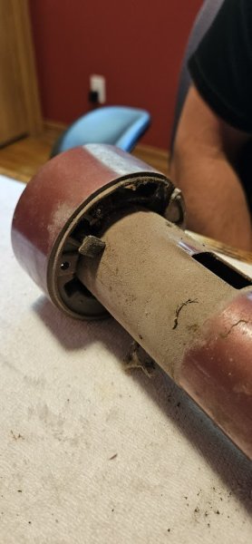
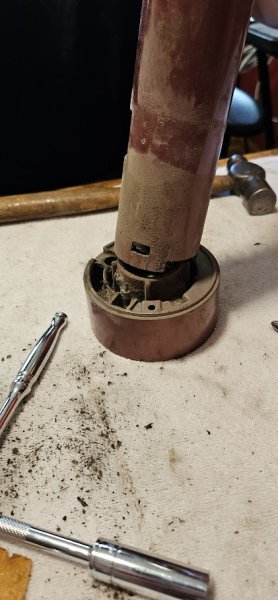
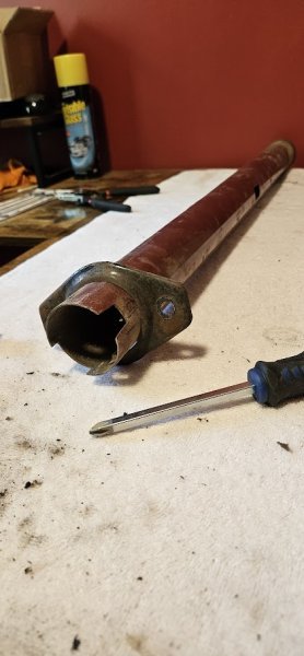
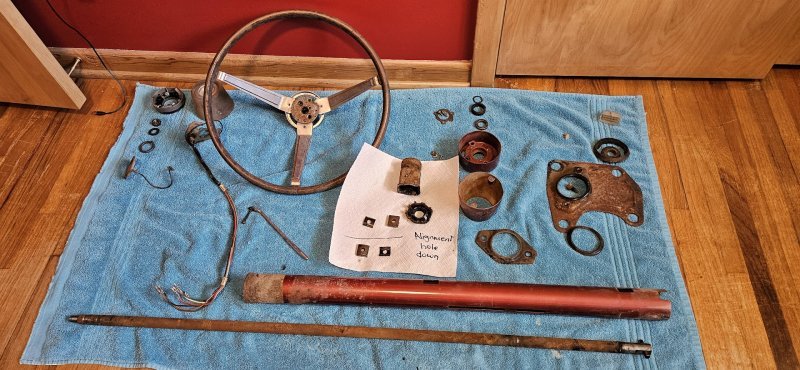
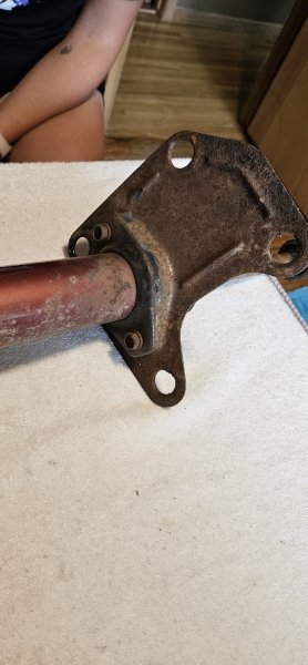
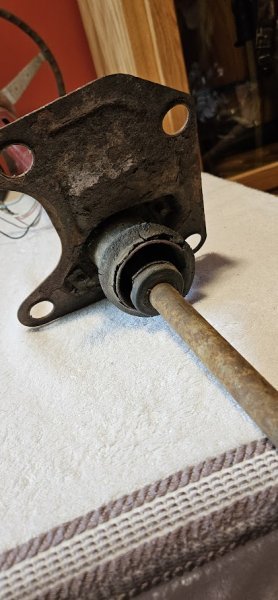
The goal is to spend the week cleaning and painting the parts and to assemble next weekend as time allows. Here is where I started. For some reason I managed to not get a picture of the entire assembly. Go figure
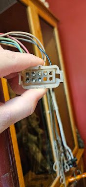
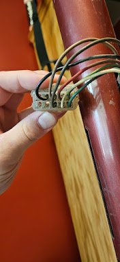
Start by pulling the pins out of the plug. There is a tab on each side that needs to be compressed then the wire pulls out the back.
Next off comes the horn pad. Quarter turn Counterclockwise and it pops right off
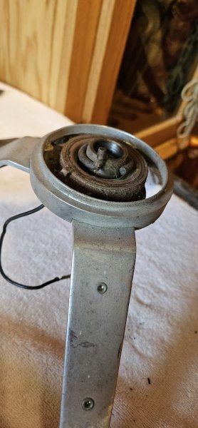
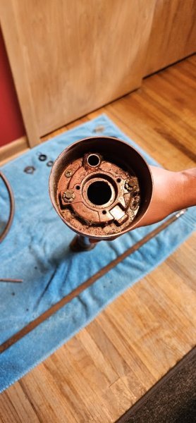
This is what's underneath
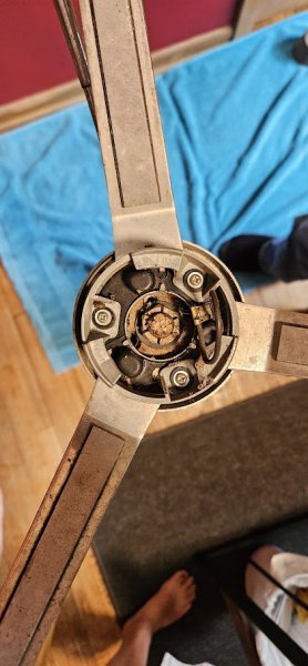
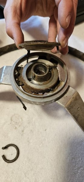
3 Phillips screws later and the pad mount lifts right up
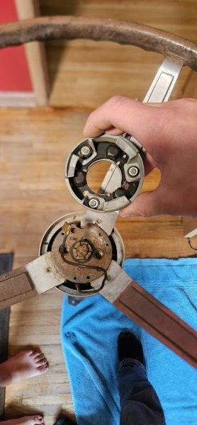
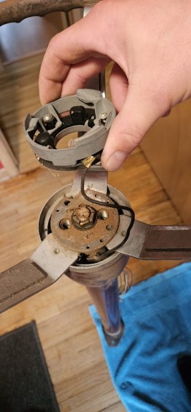
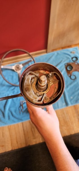
Next is to pull the steering wheel off. Using a basic puller not pictured the wheel popped right off with no issues
So that brings us to this weekend’s project. The steering column. I browsed many threads on column rebuilds but did not find one specific to 1966. Which is different than the later collapsible years. The column was very intimidating at first but was definitely a lot easier than expected. I tried to photograph and document as much as possible. Hopefully this thread helps others with any questions and if there is someone who sees something I miss please correct me!
The goal is to spend the week cleaning and painting the parts and to assemble next weekend as time allows. Here is where I started. For some reason I managed to not get a picture of the entire assembly. Go figure


Start by pulling the pins out of the plug. There is a tab on each side that needs to be compressed then the wire pulls out the back.
Next off comes the horn pad. Quarter turn Counterclockwise and it pops right off
This is what's underneath

3 Phillips screws later and the pad mount lifts right up


Next is to pull the steering wheel off. Using a basic puller not pictured the wheel popped right off with no issues

