dickdale
Well-Known Member
I've noticed that the ignition switch of my 70's Plymouth doesn't give 12 volts to a few wires when the key is in the crank position.
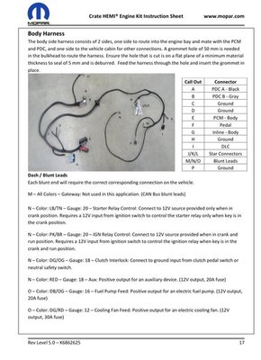
The Mopar Harness Kit (MHK) manual says:
N - Color: LightBlue/Tan wire goes to the Starter Relay Control: Connect to 12V source provided only when in crank position. Requires a 12V input from ignition switch to control the starter relay only when key is in crank position.
N - Color: Pink/Brown wire goes to the IGN Relay Control: Connect to 12V source provided when in crank and run position. Requires a 12V input from ignition switch to control the ignition relay when key is in de the crank and run position.
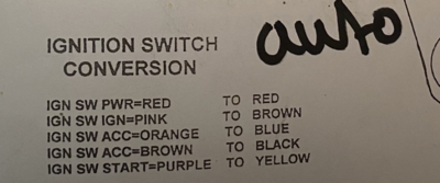
The EZ-wiring harness says:
IGN SW PWR=RED goes to RED on IGN SW
IGN SW IGN=PINK goes to BROWN on IGN SW
IGN SW ACC=ORANGE goes to BLUE on IGN SW
IGN SW ACC=BROWN goes to BLACK on IGN SW
IGN SW START=PURPLE goes to YELLOW on IGN SW
Just to be shure, does the LightBlue/Tan of MHK go to YELLOW/PURPLE and the Pink/Brown go to RED?
I probably don't want to use the PINK/BROWN wire because of the 12V signal getting lost when putting the IGN SW in the crank position?


