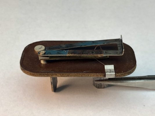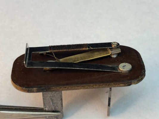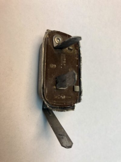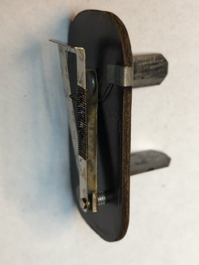


Many questions come up about instrument cluster voltage regulators, or voltage limiters as some refer to it. This factory mechanical device provides a reduced voltage for the following gauges, oil pressure, temperature and fuel gauges in our 60's era cars.. I had recently explained how it works in a different thread. Since then, found an old regulator laying around, so I cut it open to show the insides and made a couple of videos to demonstrate it working. Hope this helps understanding how it works, what it does and how small the physical movement is that opens and closes of points that create the pulsating output. Videos were made with a no load condition.
The armature, or moving part, (metal thing wrapped with wire) is the outer arm which is of a thin bi-metal material. It is wound with a very fine size of insulated resistance type wire. The far end of the winding is electrically connected to the armature closest to the points location. Battery voltage is applied to the devices IGN tab, or terminal, which is connected to the lower fixed arm with the square contact point. When cold, the points are closed and near full battery voltage is applied across this winding of resistance wire and the wire and starts to heat up. After about 1-2 seconds of initial heating, enough heat is transferred into the bi-metal material on which the other of the two electrical contact points is mounted, the round one. The far end of the armature is connected to the other outer tab, or terminal, that feeds the output voltage to one terminal, or side, of each the three aforementioned gauges. Each gauge has a resistive sender unit that is in series with each gauge to cars chassis electrical ground. The variable resistance of the senders controls the current flow to each respective gauge and thus a respective value reading.
In that initial few seconds of closed points, and higher voltage during armature heat up, near full voltage is being applied to the gauges which helps to get the gauges needles moving off zero more rapidly. As the temperature of the bi-metal elevates above ambient temperature and the physical movement causes the points to open, (only a few thousandths of an inch) turning off the voltage to the coil as well as voltage output to the gauges. After about 1/2 second, the armature material cools just enough that it moves enough and closes the points then starts the cycle all over again, repeating about every 1/2 second creating a "pulsating" voltage that is about 5 or 6 volts on average as shown on the other video.. The case ground of the coil's fine wire is wrapped around the edge of the circuit board material. Ground connection is provided by the small U shaped clip which is crimped under the perimeter outer case edges.
In this type of mechanical device, the wound resistance wire can become broken or burned up, or.. should the points become stuck in the closed condition, full voltage is always applied to the gauges and resistance wire of the regulator. The gauges operate is a similar manner of resistance wire on a bi-metal strip to create the mechanical movement. These gauges, or mechanical regulator were not intended to have a full voltage constantly applied and this condition can cause overheating and burn up the resistance wire in the individual gauges and regulator.
In short, if you haven't done so a great option is to replace the mechanical regulator with a solid state unit. The solid state units duplicate the functionality, but are far more reliable, trouble free and have protection features that protect your gauges. Did the conversion in my 66 Charger some 15 years ago.
Points video link..
Pulsating voltage demonstration...


