• When you click on links to various merchants on this site and make a purchase, this can result in this site earning a commission. Affiliate programs and affiliations include, but are not limited to, the eBay Partner Network.

Volt gauge

easyrider

Well-Known Member
Local time
6:17 PM
Joined
Nov 9, 2010
Messages
45
Reaction score
2
Location
North Carolina
I decided to change my car from amp meter to volt meter. I took the wires that went to my amp meter and ran them to my volt meter. When I hooked the battery back up I had no interior lights/radio/horn/ cranking...etc. So, I decided that the gauge must be bad and I took it back for a new one. This one is doing the same thing. I put a test light to the hot side and grounded it and there is power going to the gauge, but I put the test light to the other side of the gauge and there is nothing, and if I cross the post on the gauge the lights and everything comes back on. So, I'm going to you guys to help me sort this problem out. I hate to think I could get two bad gauges, I know it is possible, but I think the problem is simpler than a bad gauge. Can anyone give me a reason for my problem? Thanks!
 
Volt meter

A volt meter and an amp meter are not wired the same, 2 different things. You might want to check that. 383MV
 
O K that makes sense. Do you by any chance know the differences? And, what the correct way to wire a volt meter would be? Thanks!
 
The Amp gauge is virtually in inline type of gauge where the current flows through it and the voltmeter needs to be wired from 12v hot to ground.
 
Yes ^

A Ammeter is wired inline and shows either a charge or discharge depending on current flow. These are usually tied in before and draws are wired in so it shows overall charge / discharge

A Voltmeter simply reads out the amount of voltage in a system. This means you simply connect it to any 12V source and ground the other side.
 
Well I know what rolling thunder meant, but you connect it to SWITCHED 12V source. Easiest is tap into the fuse panel. Either jumper across the ammeter terminals or stack both wires on the same stud and tighten them down

SOME cars are easy to install a voltmeter in place of the ammeter. Here's a thread from over at FABO. My 67 Dart was done as pictured with a cheap SunPro voltmeter, mounted right in place of the ammeter. That voltmeter has an internal cal pot that allows you to set 14V so the needle is centered on the old ammeter scale.

Read through this thread. There are at least three types of cash clusters pictured

http://www.forabodiesonly.com/mopar/showthread.php?t=119480&highlight=ammeter+conversion
 
Easyrider, pretty sure you just pretty much ran your entire electrical system through that little volt gauge of yours. Poor thing never knew what hit it. Neither did that 2nd one you killed. Follow 440's post.
 
remember,if you are eliminating the factory amp meter you need to hook those wires together at minimum or do a bit of rewiring.
 
For checking current. You have 2 choices - either you run all the current through the meter or ya run a loop around the wire and measure the electric field (like any modern handheld ammeter). Guess which one Ma Mopar used.
 
Thanks for the wealth of information. What you are saying makes sense. So I need to take the amp wires and hook them together. Then, find another source for my switched power and ground. Can you put a wire under a fuse at fuse box for power? Or is that a bad way to get a connection?
 
Thanks for the wealth of information. What you are saying makes sense. So I need to take the amp wires and hook them together. Then, find another source for my switched power and ground. Can you put a wire under a fuse at fuse box for power? Or is that a bad way to get a connection?

You could do it that way, but it would be easier to find a wire under the dash that gets power with the ignition on.
 
Connect the two wires from the ammeter together, and connect them to the positive side of the voltmeter. Then attach a 12ga wire to a good ground.

Ammeters read current, therefore need to be hooked in series with the circuit.
Voltmeters read volts (duh), and are hooked in parallel to the circuit.
 
Connect the two wires from the ammeter together, and connect them to the positive side of the voltmeter. Then attach a 12ga wire to a good ground..

NO!! Dammit. LOL First of all you don't need a 12GA wire to ground a voltmeter

But more important, you do NOT want a voltmeter hooked to live power. If you park your car for a couple of months it will be a constant drain.
 
Connect the two wires from the ammeter together, and connect them to the positive side of the voltmeter. Then attach a 12ga wire to a good ground.

Ammeters read current, therefore need to be hooked in series with the circuit.
Voltmeters read volts (duh), and are hooked in parallel to the circuit.

Absolutely not...unless you just want the voltmeter to read voltage for that moment for testing purposes......if you leave it connected like that it will kill your battery!!!! You want to use ignition power for a permanently installed voltmeter.

And 12 gauge wire is way overkill for a voltmeter.....
 
NO!! Dammit. LOL First of all you don't need a 12GA wire to ground a voltmeter

But more important, you do NOT want a voltmeter hooked to live power. If you park your car for a couple of months it will be a constant drain.

The 12 ga wire is fine, and common, if you want to use a 14 ga wire, that is fine too. Just use what you have around the garage. The shunt resistor limits the current thru the meter, and this same shunt resistor limits the drain on the circuit.

If you want a switched voltage, find the switched voltage after the ignition switch.

PS.. I'm really glad you all are Electrical Engineers, because you really do not know what you are talking about...


LOLOLOL back to you...:sideways tongue:
 
I'm not claiming to be an electrical engineer, but.....what car have you ever been in that has the voltmeter hooked up to constant power?????? It is just a drain on the battery that you don't need.....it's going to read the same amount of voltage (ignition vs constant) and who needs it reading it when you are not in the car to look at it?
 
I'm really glad you all are Electrical Engineers, because you really do not know what you are talking about...

What are you, 12? I know exactly what I'm talking about

The 12 ga wire is................ common,:


Common? Where, in eastern Europe formerly known as the USSR?

The shunt resistor limits the current thru the meter, and this same shunt resistor limits the drain on the circuit.

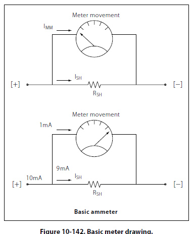
Uh, wrong again, Kimosabe. Voltmeters have SERIES resistors known as multipliers. Only current meters have shunts, which are in parallel.


A simple voltmeter circuit:

49484276ng2.png


A basic current meter and shunt resistor

fig10-142.jpg
 
I'm not claiming to be an electrical engineer, but.....what car have you ever been in that has the voltmeter hooked up to constant power?????? It is just a drain on the battery that you don't need.....it's going to read the same amount of voltage (ignition vs constant) and who needs it reading it when you are not in the car to look at it?

I didn't say that is HAD to be, I just stated how to hook it up in general. You ca also hook it to switched power, it doesn't really matter.

When you have 1mA FS meter, and measures 18V full scale, it will have a series resistor of 18K Ohms. Now, when the car is running, and charging at lets say 14.2v, that will draw 788 uA (0.788 mA). When the motor is not running, the meter will draw 666 uA (0.666 mA). It would take a very long time to drain a car battery with that load.
 
What are you, 12? I know exactly what I'm talking about

Actually, I am that plus a few more tens...

Common? Where, in eastern Europe formerly known as the USSR?

Yes, common. Most cars use 22, 18, 14, 12, and larger, but a fair amount of 12 is used on cars. Oh, and Eastern Europe also had the DDR, Czechoslovakia, Yugoslavia, etc...

Uh, wrong again, Kimosabe. Voltmeters have SERIES resistors known as multipliers. Only current meters have shunts, which are in parallel.

On this you are correct, I mis-spoke my terms. The series resistor is derived by how much current the meter reads full scale, and the voltage you want full scale to represent.

When you have 1mA FS meter, and measures 18V full scale, it will have a series resistor of 18K Ohms. Now, when the car is running, and charging at lets say 14.2 v, that will draw 788 uA (0.788 mA). When the motor is not running, the meter will draw 666 uA (0.666 mA). It would take a very long time to drain a car battery with that load.

I found articles that said to hook it hot, and others that said switched. We are arguing semantics here. The voltmeter circuit is the best choice, and needs to be hooked up in parallel to the circuit. The meter should already have the series resistor inside of it too.

On a side note, I would hook it switched myself, but it really doesnt matter.
 
Auto Transport Service
Back
Top