• When you click on links to various merchants on this site and make a purchase, this can result in this site earning a commission. Affiliate programs and affiliations include, but are not limited to, the eBay Partner Network.

Four wheel disc conversion on my 64 Polara

Glenwood

Well-Known Member
Local time
6:56 PM
Joined
Jun 19, 2015
Messages
2,929
Reaction score
2,848
Location
Kawartha Lakes, Ontario
With a more power available than the old poly318 had, I decided it was time to upgrade the suspension and braking system on the ’64, now that I’m done with the sheet metal work, engine & cooling system (which took longer and cost more than imagined!) The single can master cylinder and 10 inch drum brakes felt soft and made me a bit nervous at times.
mastcyl64.jpg
IMG_3573.JPG


Without many options up here in in the great white north, though national moparts does sell a package for the front, I settled on Dr. Diff’s offering.

1175front.jpg
Rear_disc_kit_01.jpg


Wanting to do a 4 wheel disc conversion meant the rear end would need to have flanged styled axles instead of the original tapered axles available in ’64. I had already swapped the rear end with a ’70, but it was still a bit too wide for the 275’s in the wheel wells, even with 4.5” back spacing. However, there is enough clearance to the leafsprings for over 5” backspace.

IMG_5146.JPG

20191224_172700.jpg


I found a ’63 B-body rear end for sale locally and picked it up. This housing is approx. 1.5” narrower than the ’70. I ordered new axles from Cass as well. After checking the gears and replacing the front seal on the 3.23 741, I cleaned, painted and installed back on the 63 housing. The flange studs for the pumpkin were in rough shape so these were replaced. For the brake conversion, longer axle tube flange studs are needed, so these were replaced too.

newaxles.jpg

20200101_115312.jpg


Cass was able to pull these items together and ship them to me in a week, while I was in the USA on a business trip recently.


The front brake kit has:

· new spindles (73-76 Duster/73-74 Challenger). You have to reuse your two large mounting bolts.

· Rotors from a 78 Cordoba

· Calipers 82 Diplomat

· Hoses & Timken bearings.

I ordered new front SS brake lines, Mopar aluminum dual master cylinder with a 15/16” bore & 2 to 4 bolt adapter, distribution block, master cylinder lines


The rear end brake kit has:

· Aluminum caliper brackets

· Rotors for a Toyota Cressenda

· Calipers with E-brake for a 98 Cobra

· Braided hoses

· Optional New E-brake cables
 
I also ordered new 1.03” torsion bars from PST and a new 1-1/8” Hellwig anti-sway bar through Summit. Shocks to be ordered later as sourcing Bilsteins up here seems impossible.

F142752786.jpg

20191219_190015.jpg


Having completely dismantled, cleaned and painted all of the components on the car a few years ago, it was easier to dismantle this time.

The torsion bars came out without too much trouble using the tool I made, after the bottom bolts for the shocks were removed and the upper rubber bumpers were removed.

The front spindles came off easily and I was able to use my pitman arm puller to easily separate the upper ball joints. The knuckle, lower ball joint and tie-rod did not need to be dismantled further. After a little grease clean up, the spindles were installed with the caliper mounts facing rearward. Torquing the upper ball joint (125lbs) was difficult with the spindle unbolted. There isn’t enough room to get a socket and TQ wrench on otherwise. I found that it was easier to turn the spindle part way and insert only one bolt through the spindle and lower ball joint. This allowed more access and was much easier. Original knuckle large bolts and castle nuts (to back) were installed and torqued to 100lbs.

spindle.jpg


The rotors came with races installed made of fine chinesium. The dr. recommends replacing the races with the ones that come with the new Timken bearings. It was a bit tricky to pop them out of the rotor. I had a 1”+ SS round bar that was a perfect fit to pop out the outer small race, but the large one was more difficult. I used a large drift to pop it out without scoring the sides of the rotor. Installing the new races was easy using the seal/race driver kit I finally broke down and bought. The inner seal does not come with instructions and could go in either way. It’s been a while since I worked on these types of rotors, so I could not remember how to orientate it. It turns out the rubber portion is to stick out towards the knuckle to seal out debris from entering the bearings. These are a tight fit and could not be tapped in side to side. I found a large sleeve from my ball joint press fit the seal nicely.

races.jpg
timken.jpg
rotorseal.jpg


Before I packed the inner bearings and installed in the rotor, I tried sliding them on the spindle. Good thing I did as they are too tight. I took some 600 grit and knocked the spindle diameters down enough to slide on the bearings with a bit of grease.

20191228_200222.jpg
20191228_200231.jpg
 
Pre-bent SS front brake lines fit nicely and assembly went smoothly, though the hoses were tricky to curl in the right direction to install on the caliper properly. I wanted to be sure they wouldn’t get pinched or rub on any sharp edges. I blew out the front to back brake line with compressed air before attaching to the distribution block.

dist block.jpg


The old master cylinder rod was difficult to remove. Mounted in a vice, the rod simply would not pry out of the MC, so I found a tire iron fit nicely through the rod’s eyelet, where a few taps with a hammer on the tire iron propped it free, squirting fluid in the process. The spring and boot were removed, a new rubber washer from Dr Diff was installed on the rod and inserted into the new MC. I installed the adapter and MC to check the rod length and it was perfect.

mastcyl64 rod.jpg
mastcyl64 rod1.jpg
mastcylplate.jpg
20200109_183809.jpg


Rotors, bearings were greased, tightened, backed off and torqued to 90inches before installing cotter pins. The caliper brackets were installed using the button head bolts supplied, loctite and torqued according to Dr. Diff’s specs. The calipers went on easily, though DR Diff’s instructions tell you to bend the outer pad tabs with a hammer to snug them up and keep them from rattling. I removed the caliper sliding pins first to check/add silicon grease. I installed the brake dust shields and greased the joints. The calipers are very close to the 15 inch rim and trimmed off the stick-on balance weights inside the rim.

20200109_183832.jpg
 
The new torsion bars are fat! I found the passenger side difficult to install, having to force the adjuster LCA pivot down a bit and then realized the headers that barely cleared the original bars are too close to the fatter bars. Some heat and encouragement opened up the space a bit on the passenger header. Looks like the pitman and idler are rubbing the headers as well under certain conditions, so these areas were massaged too.

No way the new seals would go on over the bars. I boiled water and let them sit in it, but they were simply too tight. The old seals were replaced a couple of years ago and I just reused them instead.
 
Last edited:
The rear was fairly simple, but the instructions are vague. Basically the pumpkin goes on first, the caliper mount adapter brackets 2nd without gaskets and facing rearward, then the axles. The adapter bracket holes have to face inward for proper clearance. I had them on backwards at first, since the instructions do not point out the proper positioning. On goes the rotors, caliper mounts and then the calipers. Washers are supplied to help center the claipers over the rotors. I found one side needed thin washers and the other side need the thicker ones. Bent up the brake lines to the new block and mounts on the caliper bracket.

20200101_173138.jpg
20200101_173150.jpg
20200102_195008.jpg
20200102_195015.jpg


Test fit the wheels...lots more room and looks better to me.

20200102_195029.jpg
20200102_195043.jpg
20200109_183914.jpg
 
The parking brake cables from Dr Diff that needed to be ordered for this conversion did not fit right. The sheath was too long and the cable stickout was too short for the intermediate cable. No matter how you route the cable, the stickout was approx. 5/8" short, so the int-med cable equalizer wound not reach the front cable adjuster stud. I measured for replacement cables and Cass sent them free of charge, but I don't think he was too happy about it. He claimed that the spec for his cables always fit, but I have no idea why they would not work on this car with everything in stock positions. The cables seat only one way as the metal ends are different diameters, but you would notice this pretty quick when you try to put the c-clips on. The new cables I spec'd fit perfectly and placed the equalizer in the middle of the adjuster stud as I would expect. I took about 5" off of the jacket length and added a little to the steel cable.

20200106_190256.jpg

20200108_073949.jpg
20200123_181242.jpg
20200106_190230.jpg
 
Bench-bled the master cylinder and then the system. Cass recommends Dot4 fluid, so I went with that. They still seem soft, but I won't get a chance to test them for a few months once the snow is gone.

On to the sway bar...
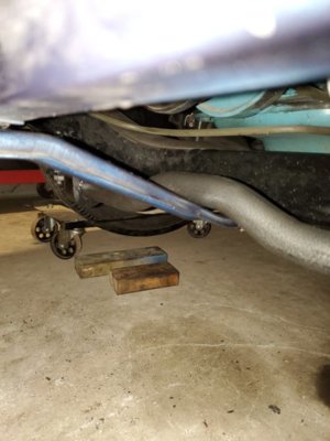
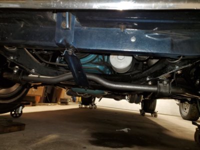
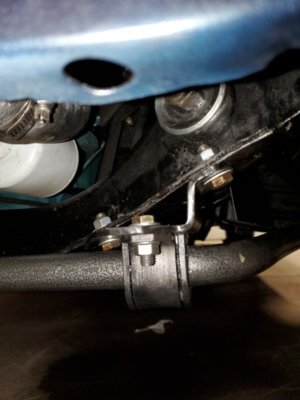
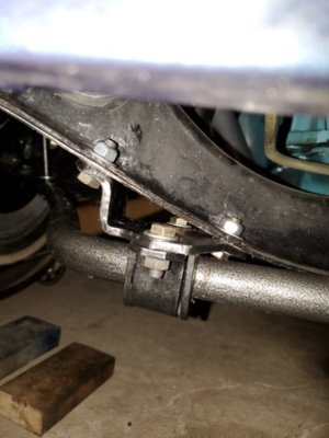
The Hellwig 1-1/8" solid bar seems like a nice piece. The brackets and parts look like heavy duty pieces. I discovered the endlink bushings were all missing. Looks like someone ordered the bar, sliced the bag, took the bushings and sent it back to be resold. Lucky me. Summit was very slow to respond and took a phone call before they got after Hellwig to send me some bushings. A month later, they arrived and I went to work.

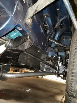
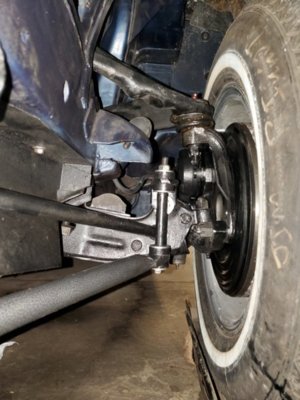
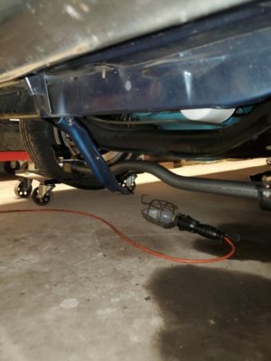
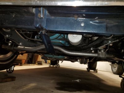
The rad support bracket has to be removed while setting it all up. The center bend is very close, in fact too close to the bracket and I will have to space the support bracket down a bit. With the car on its wheels, the right angled brackets are installed to the shock bolts (new longer ones)and then the endlinks. Trying to find the proper angle of the endlink brackets to properly center the bar is a pain. Once that is done and everything snugged up, the other bar brackets can be placed. These are left and right orientation. Drilling 3/8" holes upside down is always a treat!

20200131_165700.jpg 20200131_165732.jpg 20200131_165745.jpg 20200131_200322.jpg 20200131_200346.jpg 20200131_200322.jpg 20200131_200332.jpg 20200131_200353.jpg
 
Nice documentation job for the rest of us. Cass is the man, I wish I knew him and his parts 25 years ago.I think he may have been a teenager back then though..
 
Glenwood, I have followed you on your build. You have done a great job and you should be proud of it. Of course I'm alittle bias but truly appreciate your time to show us all how it is done.
 
Just put a front disc conversion on my Bee and wish Cass would have told me to replace the races on the rotor. To late now.....
 
Glenwood, I have followed you on your build. You have done a great job and you should be proud of it. Of course I'm alittle bias but truly appreciate your time to show us all how it is done.

You're too kind Barry. These parts are pretty simple to install, even for an old sparky like me. I hope they work!
 
Just put a front disc conversion on my Bee and wish Cass would have told me to replace the races on the rotor. To late now.....


Truthfully, I read it on a number of other posts from other sites, as it's not mentioned in the instructions. Otherwise I would have done the same thing, though it probably won't hurt them too much.
 
Pre-bent SS front brake lines fit nicely and assembly went smoothly, though the hoses were tricky to curl in the right direction to install on the caliper properly. I wanted to be sure they wouldn’t get pinched or rub on any sharp edges. I blew out the front to back brake line with compressed air before attaching to the distribution block.

View attachment 903550

The old master cylinder rod was difficult to remove. Mounted in a vice, the rod simply would not pry out of the MC, so I found a tire iron fit nicely through the rod’s eyelet, where a few taps with a hammer on the tire iron propped it free, squirting fluid in the process. The spring and boot were removed, a new rubber washer from Dr Diff was installed on the rod and inserted into the new MC. I installed the adapter and MC to check the rod length and it was perfect.

View attachment 903551 View attachment 903552 View attachment 903553 View attachment 903554

Rotors, bearings were greased, tightened, backed off and torqued to 90inches before installing cotter pins. The caliper brackets were installed using the button head bolts supplied, loctite and torqued according to Dr. Diff’s specs. The calipers went on easily, though DR Diff’s instructions tell you to bend the outer pad tabs with a hammer to snug them up and keep them from rattling. I removed the caliper sliding pins first to check/add silicon grease. I installed the brake dust shields and greased the joints. The calipers are very close to the 15 inch rim and trimmed off the stick-on balance weights inside the rim.

View attachment 903555
Glenwood on the front for the hose you got to use the stock mounting brackets.
 
The rear was fairly simple, but the instructions are vague. Basically the pumpkin goes on first, the caliper mount adapter brackets 2nd without gaskets and facing rearward, then the axles. The adapter bracket holes have to face inward for proper clearance. I had them on backwards at first, since the instructions do not point out the proper positioning. On goes the rotors, caliper mounts and then the calipers. Washers are supplied to help center the claipers over the rotors. I found one side needed thin washers and the other side need the thicker ones. Bent up the brake lines to the new block and mounts on the caliper bracket.

View attachment 903556 View attachment 903557 View attachment 903558 View attachment 903559

Test fit the wheels...lots more room and looks better to me.

View attachment 903560 View attachment 903561 View attachment 903562
I have a thought what's your input. I'm going to put 3m clear gravel guard on the panel that flattens out behind rear wheels.
 
Thanks for sharing Glenwood! I might do the upgrade someday but I'm good for now. I like dealing with Cass. He's really helped me out in the past and just recently.

I have a sweet spot for the '64s. My first Mopar when I was 18 :D
 
Auto Transport Service
Back
Top