You are using an out of date browser. It may not display this or other websites correctly.
You should upgrade or use an alternative browser.
You should upgrade or use an alternative browser.
Charging issues
- Thread starter 78cordoba
- Start date
- Local time
- 10:04 PM
- Joined
- Sep 5, 2017
- Messages
- 1,921
- Reaction score
- 3,086
- Location
- 6720 Cuff Road Jackson, MI 49201
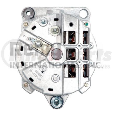
Did a little more digging on your alternator and from the back of the case it does look like the small stud is for a ground wire (I would verify that). The other thing I noticed is that the Field wires are marked F1 and F2. From your pictures it looks like the FLD wire is hooked in correctly. Any chance it is spun 180 degrees. The connector may be a one way style with a release so it can't get hooked up backward. The little ground stud, if that is what it is being used for, there should be a small wire that should go to it (guessing since I can't find a wiring diagram in PDF for the charging system). Not sure if that wire would just ground the case or if it is also a reference signal wire. I will do a little more digging in the AM
78cordoba
Well-Known Member
Yes I noticed it said grd by it. That's what I had to use to ground the alternator case. It had too much paint on the case it's self and couldn't get it to ground without using the small stud.
- Local time
- 10:04 PM
- Joined
- Sep 5, 2017
- Messages
- 1,921
- Reaction score
- 3,086
- Location
- 6720 Cuff Road Jackson, MI 49201
I did find the wiring diagram for a 1976 cordoba but it is not that much help.

- Local time
- 10:04 PM
- Joined
- Sep 5, 2017
- Messages
- 1,921
- Reaction score
- 3,086
- Location
- 6720 Cuff Road Jackson, MI 49201
The green wire coming out of the voltage regulator (blue connector) runs to the back of the alternator. On the off chance that this wire is broken/melted/messed up you may want to back stab your ground to the green wire at the alternator connection. Just be aware that the two field wires are very close together and you only want the green one grounded to test if increase in RPM will give increase in volts. This will eliminate the 4 or 5 foot of green wire from the circuit.
- Local time
- 10:04 PM
- Joined
- Sep 5, 2017
- Messages
- 1,921
- Reaction score
- 3,086
- Location
- 6720 Cuff Road Jackson, MI 49201
From the memory on the wires it looks correct. Is the back spade a little bigger than the front?
- Local time
- 10:04 PM
- Joined
- Sep 5, 2017
- Messages
- 1,921
- Reaction score
- 3,086
- Location
- 6720 Cuff Road Jackson, MI 49201
For the two spades T1 and T2 that connector clips to; T1 should be from the ing switch and T2 should be the voltage drop sense (the green wire) Problem is I can't find a diagram that shows which is which.
- Local time
- 10:04 PM
- Joined
- Sep 5, 2017
- Messages
- 1,921
- Reaction score
- 3,086
- Location
- 6720 Cuff Road Jackson, MI 49201
Okay, still looking for the correct dang wiring diagram. Sorry that I'm not being much help to you. 
- Local time
- 10:04 PM
- Joined
- Sep 5, 2017
- Messages
- 1,921
- Reaction score
- 3,086
- Location
- 6720 Cuff Road Jackson, MI 49201
The electronic one:

It is an older diagram so not sure about the color codes. I see blue with white trace and I think yours is just blue
It is an older diagram so not sure about the color codes. I see blue with white trace and I think yours is just blue
- Local time
- 10:04 PM
- Joined
- Sep 5, 2017
- Messages
- 1,921
- Reaction score
- 3,086
- Location
- 6720 Cuff Road Jackson, MI 49201
Sorry, I don't know the internals just that one spade will tell the alternator to increase output. Other than that I am flying blind. The parts store may have more info on it.
Micah Pohlman
Well-Known Member
Yes there should be a ground wire that goes all the way over to the battery. But it also gets bolted to the engine via A/C bracket on its way over there. This might be enough because the 100 amp alt has vibration isolating mounts.Also the smaller stud on my alternator is not hooked up to anything should it be grounded?
You can see part of the ground wire just under the heater hoses in this picture. It's the best I can find on my computer right now.

78cordoba
Well-Known Member
yeah gave this a try still no luck i might have the alternator tested again just to be sureThe green wire coming out of the voltage regulator (blue connector) runs to the back of the alternator. On the off chance that this wire is broken/melted/messed up you may want to back stab your ground to the green wire at the alternator connection. Just be aware that the two field wires are very close together and you only want the green one grounded to test if increase in RPM will give increase in volts. This will eliminate the 4 or 5 foot of green wire from the circuit.
78cordoba
Well-Known Member
Alternator is working as it should now. I feel like an idiot I think it was the alternator not grounding issue all along. Along with not having a full charge on the battery and the system wouldn't work properly but I'm at like 12.6 with the key off now and like 14 at idle thanks for all your help guys
Similar threads
- Replies
- 20
- Views
- 1K
- Replies
- 14
- Views
- 629


