• When you click on links to various merchants on this site and make a purchase, this can result in this site earning a commission. Affiliate programs and affiliations include, but are not limited to, the eBay Partner Network.

1968 Roadrunner gauge cluster circuit board pins came off..

mrbone

Well-Known Member
Local time
8:12 AM
Joined
Nov 8, 2017
Messages
73
Reaction score
25
Location
Minnesota
RR broke board.jpg
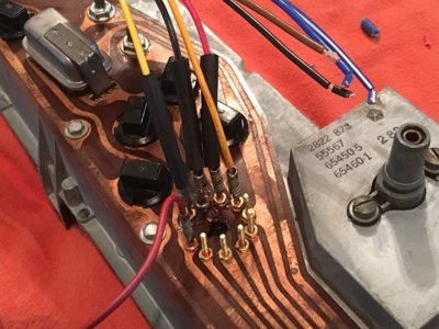
Anyone ever run into this?
My harness pulled four pins out of my gauge cluster circuit board.
Has anyone ever soldered these back on?
Not sure where to source a replacement board?

THANKS!!
 
Last edited:
Yearone has a replacement board for $150.

I also have a ‘68 standard cluster for sale for $120 shipped, which had all the circuit-touching components working when pulled ;)

You CAN solder the pins back on, as long as you are comfortable soldering on a printed board. You have to be careful not to bridge any circuits or burn the print.
 
Lots of paste flux and not too much heat in soldering.
I've fixed several from b body to fwd l body mopar.
 
If have original pin put another pin inside that will go into board 1/16". Will make it stronger.
 
I've repaired them but it is still sketchy. I'd rather buy new and be sure of the connections.

My fix was to solder some copper strand wire into the back of the pin then solder it to the board. Caution....if the solder joint behind the pin is too thick it can contact the metal gauge housing and cause all kinds of issues. There is suppose to be a gasket between the two.
 
I have replaced missing/broken pins by using eyeglass screws to secure the pins to the board. The pins themselves are hollow so inserting screws from the back pulls the pins tight to the board. It's important to use the correct size screw so as not to spread the pin too much. Eyeglass kits with assorted screws are available at any drug store. Once tightened you can also solder if needed.
Pin repair ll.JPG
 
I've repaired them but it is still sketchy. I'd rather buy new and be sure of the connections.

My fix was to solder some copper strand wire into the back of the pin then solder it to the board. Caution....if the solder joint behind the pin is too thick it can contact the metal gauge housing and cause all kinds of issues. There is suppose to be a gasket between the two.
A shade tree insulating gasket can be made with parchment paper and kapton tape.
 
I inserted a Brad nail through the back and cleaned and fluxed everything well. A good solder iron on the top of the pin and apply the solder at the bottom where the break occurred. When it gets warm enough the solder will wick up the pin.
 
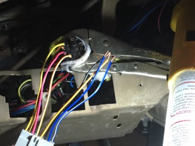
So, after assembling entire dash with brass screws in place of the old pins. I found the 'new' pins were not contacting the original plug very well- flickering lights.
I decided to solder a new plugin harness between the original.
Rather than removing the screws I used them to solder wires directly to them. Then on the Female side I soldered wires to the original plug. Used heatsink on all connections, now after installation lights work 100%.
Not the cleanest solution, but simple, cheap and I now have a reliable plug for disassembly.
CHEERS!

1sm.jpg 2sm.jpg
 
Last edited:
I used tiny copper nails and after I soldered their heads to the circuit board, I wrapped them with single strand 22 gauge wire and soldered it to the nail to make them the same diameter as the original pins. Pretty easy fix.
 
You can get solder ferrels and flow over the screws to build up contact area. The wire build up works too
 
Auto Transport Service
Back
Top