• When you click on links to various merchants on this site and make a purchase, this can result in this site earning a commission. Affiliate programs and affiliations include, but are not limited to, the eBay Partner Network.

2 gauge problems

mjb765

Well-Known Member
Local time
9:10 PM
Joined
May 10, 2010
Messages
319
Reaction score
77
Location
De
First--I am just making sure on this one...if you ground the wire coming off of the fuel tank sending unit and the gauge reads full, but only reads 3/4 when connected--even if the tank is full, then I am guessing the sending unit is bad?

And second...The ammeter is bouncing between either side of the +20 line on anthing over 2000 rpm. Checked voltage at the battery and it's 13.4 at idle and sometimes can hit 15v when I rev it. When I say bouncing--I don't mean just moving back and forth--this thing is violently wiggling, or jumping. Just happen to replace the battery today since it failed load test...but that didn't change the gauge movement. Any ideas?
 
As for the 3 gauges with sending units, fuel, temp, & oil pressure:

The sending units all provide a varying resistance to the low side of the gauge. Usually this resistance is between 10 ohms (full or high on gauge) to 70 ohms (empty or low on gauge).

A quick check a lot of people use is to ground the wire (0 ohms) at the fuel tank to see if they get a "Full" reading on the fuel gauge. This works if you don't keep it grounded TOO LONG. It is possible to destroy the gauge and possibly the voltage limiter on the back of the instrument panel if directly grounded too long. A better way to test the gauge is with a potentiometer (variable resistor) or just use a 10 ohm resisitor at the sending unit wire to ground. This should give you a "full" reading without damaging your gauge or limiter.

To visualize the circuit, the battery voltage (+12V) is applied to one terminal of the gauge, passes through the gauge to the other terminal which is attached to the wire that goes directly to the appropriate sending unit (a variable resistor). The sending unit is also grounded to the chassis in some manner which then completes the circuit. As the circuit resistance increases or decreases (sending unit) the current through the circuit increases or decreases and the needle on the gauge moves correspondingly.

As for your ammeter, this gauge is totally independent of the other 3. If I understand you correctly, your ammeter seems to be working OK until you go above 2000 RPM, and then it starts its wild dance.

Your voltage at idle is normal and even the 15 V when you rev it is not unusual. The "bounce" might be caused by an old style "points" voltage regulator if that is what you have on the car. You could try replacing it with a new style "solid state" VR. Make sure you have a good clean ground between the VR and the chassis regardless of which type of VR you have.

If it is not the VR, my next guess would be a problem with the alternator itself. Also make sure the connections on the back of the ammeter are snug and not corroded. :eusa_think:
 
Thanks for the detailed response. I did ground the wire at the sending unit and the gauge went to full. So that would mean a bad sending unit.......

I will look at the voltage regulator. Is there any way to tell what type it is by looking at it?
 
When the tank is empty does the fuel gauge read 1/4 or E. I have seen the float arm get bent or the float go bad in the tank. If that's the case, a simple bend of the arm can fix the problem or a new float. Or, for your peace of mind, replace the whole unit. Be sure the new unit reads full and empty, it may need adjustment itself
 
When the tank is empty does the fuel gauge read 1/4 or E. I have seen the float arm get bent or the float go bad in the tank. If that's the case, a simple bend of the arm can fix the problem or a new float. Or, for your peace of mind, replace the whole unit. Be sure the new unit reads full and empty, it may need adjustment itself

Not sure yet...haven't owned the car long enough!! I do know the tank is full right now and the gauge reads 3/4...but it goes past full when I ground the sending unit wire.
 
That's what Mopars&Missles was talking about. The sending unit in the tank goes from 90 Ohms (Empty) to 10 Ohms (full) so when you ground the wire you should go over full. If you put a 10 Ohm resistor from the wire to ground you should get a full reading or at least close without pegging the gas gauge.
 
Yes..I understand that...so since the gauge is responding to the ground test, I am thinking the sending unit is bad--or out of adjustment. But if I am taking it out anyway, I will just order a new one and put that in.
 
Yes..I understand that...so since the gauge is responding to the ground test, I am thinking the sending unit is bad--or out of adjustment. But if I am taking it out anyway, I will just order a new one and put that in.

I'm thinkin' your thinkin' right. Sending unit not necessarily bad, but might need some tweakin' to make it read correctly.

If the sender is an original, DO NOT throw it away. Lot's of guys have better luck repairing the originals than getting an aftermarket repop to work correctly.

JFYI, readings from one of my fuel gauges (for comparision purposes to yours)

Empty = 68.0 ohms
1/8th = 49.0 ohms
1/4th = 40.0 ohms
3/8th = 31.0 ohms
1/2 = 25.5 ohms
5/8th = 21.0 ohms
3/4th = 17.5 ohms
7/8th = 14.0 ohms
Full = 12.0 ohms
 
Old Style Voltage Resistor

Thanks for the detailed response. I did ground the wire at the sending unit and the gauge went to full. So that would mean a bad sending unit.......

I will look at the voltage regulator. Is there any way to tell what type it is by looking at it?

MJB,

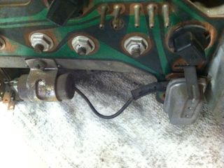
Here's a pic of the stock voltage regulator (from a '70 in this case). They're hard to test, as they essentially open and close the circuit many times per second (minute?) to get a 12 volt source to AVERAGE 4.5 volts. If you hook it to a meter it will bounce all over the place. But hook it to a bulb and the bulb will glow bright and dim - good old analog test...

RT Engineering (rt-eng.com) makes a new digital VR for about $50. Spendy, but cheaper than all new gauges.

The VR is on the right in the pic: the little grey rectangle about the size of a Sees chocolate with the metal strap coming off the top. In the photo it is connected by a wire to it's ground resistor...

Greg
 

Attachments

  • IMG_0478.jpg
    IMG_0478.jpg
    19.9 KB · Views: 323
MJB,

Here's a pic of the stock voltage regulator (from a '70 in this case). They're hard to test, as they essentially open and close the circuit many times per second (minute?) to get a 12 volt source to AVERAGE 4.5 volts. If you hook it to a meter it will bounce all over the place. But hook it to a bulb and the bulb will glow bright and dim - good old analog test...

RT Engineering (rt-eng.com) makes a new digital VR for about $50. Spendy, but cheaper than all new gauges.

The VR is on the right in the pic: the little grey rectangle about the size of a Sees chocolate with the metal strap coming off the top. In the photo it is connected by a wire to it's ground resistor...

Greg

Yes, that is the Voltage LIMITER (yes, a regulator, but the factory calls it a "limiter") on the back of the instrument panel and yes, RTE makes a very good solid state replacement BUT:

I think the second part of the OP question dealt with the wild fluctuation of the ammeter. The voltage LIMITER does not have anything to do with the ammeter and since his other 3 gauges are working, his LIMITER is therefore working. However, the underhood voltage REGULATOR (that I was referring too) can cause ammeter fluctuations. We were thinking if he had an original voltage REGULATOR on the car yet, it would be the old style points type, much the same as the voltage LIMITER is a points type that you are referring to. The REGULATOR could be operating erratically causing the ammeter fluctuations.

The + and - 20 amp swings sounds like the points of the voltage REGULATOR are opening and closing (turning on and turning off) but not as quickly as it should to maintain a fairly constant control of the current. Its just a guess, don't hold me to it.

And No, I don't think it is easy to tell the difference between the original points style and the new solid state type without removing the cover of the REGULATOR and looking inside.

As far as that goes, he didn't even tell us what year/model car he's working on. That alone will cause differences in the voltage REGULATORS.
 
...In the photo it is connected by a wire to it's ground resistor....

You were correct with everything except this statement. That is a NOISE SUPRESSION CAPACITOR (on the bottom left) that is attached to the LIMITER. Its function is to reduce/eliminate electrical noise spikes on the +12V bus that would cause interference with the RADIO, especially an AM radio.
 
The + and - 20 amp swings sounds like the points of the voltage REGULATOR are opening and closing (turning on and turning off) but not as quickly as it should to maintain a fairly constant control of the current. Its just a guess, don't hold me to it.

And No, I don't think it is easy to tell the difference between the original points style and the new solid state type without removing the cover of the REGULATOR and looking inside.

As far as that goes, he didn't even tell us what year/model car he's working on. That alone will cause differences in the voltage REGULATORS.

You're right--I just realized that!!!! Sorry...It's a 69 Super Bee.
 
Solution to alt volt reg problems-

41-aG0961CL._SL500_AA300_.jpg


SMP VR-128 regulator, also made by a few others-can be found using parts interchange resource. The original points type regulator will have two fuse links on the bottom that look like ballast resistor links (or maybe they are-don't remember).

images
 
I've used the regulator in the top photo, that is the MP3690732 version for race applications only. Depending on how much you drive it, I would not recommend it for street use. You can cook the battery with it. Below is from the MP catalog concerning that regulator.


B. Voltage Regulator, Constant Output
To ensure your ignition and electrical systems can provide maximum
performance, install a Mopar Constant Output Voltage Regulator.
Voltage is held at a constant 13.5 volts. For race applications only.
1 P3690731 Voltage Regulator, Constant Output, 1970 and Newer
V8, Race
1 P3690732 Voltage Regulator, Constant Output, to 1969, Race


An aftermarket solid state replacement is probably the best choice. Unfortunately, I don't have a part number for you. Sorry.
 
No problem...I will try to locate a solid state VR.

I am also going to order a solid state limiter from RTE. Now I will go figure out how to get the dash out. Never did that on a B body before....


Thanks for the advice.
 
Last edited:
I've used the regulator in the top photo, that is the MP3690732 version for race applications only. Depending on how much you drive it, I would not recommend it for street use. You can cook the battery with it. Below is from the MP catalog concerning that regulator.


B. Voltage Regulator, Constant Output
To ensure your ignition and electrical systems can provide maximum
performance, install a Mopar Constant Output Voltage Regulator.
Voltage is held at a constant 13.5 volts. For race applications only.
1 P3690731 Voltage Regulator, Constant Output, 1970 and Newer
V8, Race
1 P3690732 Voltage Regulator, Constant Output, to 1969, Race


An aftermarket solid state replacement is probably the best choice. Unfortunately, I don't have a part number for you. Sorry.

That's why I gave him the part number VR-128-it's not the MP you reference.
 
Sorry, that top photo looked like the MP unit. My bad. :icon_confused:

No problem. Honestly, I wouldn't suggest anything that I hadn't researched myself-and in fact, I have a VR128 on my R/T, and it works great. Super easy install to boot, literally a plug in. For what it's worth, I share management at large Fleet shop for the University of Minnesota. Been doing the car thing now for 35 years.
 
Auto Transport Service
Back
Top