• When you click on links to various merchants on this site and make a purchase, this can result in this site earning a commission. Affiliate programs and affiliations include, but are not limited to, the eBay Partner Network.

#4 Intake I found the leak

.451 & .455 lobes.
Not sure what measurement is from base circle to bottom of lifter bore. I’ll have to find a way to check that.
I thought it would be at the top of the lifter bore where I’d have an issue. Not the bottom.
I am going to call my builder today and get his input.
 
I measure the Comp lifter wheel at .800"
 
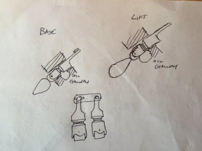
My diagram is not great. But as you can see it is at max lobe lift at the bottom of the lifter bore where the potential issue is, or is it?

View attachment 590464

02803724-79FA-4BF2-A29E-99943E12982D.jpeg
 
My diagram is not great. But as you can see it is at max lobe lift at the bottom of the lifter bore where the potential issue is, or is it?
The problem would either be that the top of the oil band is to high allowing the oil path to connect with the cutout for the roller wheel at base circle. Or the bottom of the band to low/roller cutout to high doing the same at max lift. Either way the oil would be leaking into the cam tunnel.
Doug
View attachment 590464

View attachment 590471
 
I spoke with my builder and he figure I’ll be fine. If there is a problem we will find it on the dyno.
 
My diagram is not great. But as you can see it is at max lobe lift at the bottom of the lifter bore where the potential issue is, or is it?

View attachment 590464

View attachment 590471
By that drawing, the wheel cut out will be exposing the oil galley at max lift.
I suspect you’ll notice that on the oil pressure gauge. Is the lifter actually going that high?
 
By that drawing, the wheel cut out will be exposing the oil galley at max lift.
I suspect you’ll notice that on the oil pressure gauge. Is the lifter actually going that high?

It is very close. I thought a Comp lifter has a smaller wheel but I don’t think .0125” will make enough difference from what I already have. I guess when we get it on the dyno, we can see if it will work?
 
If your block has bushings it really isn’t. What I am trying to do takes a bit more time.
 
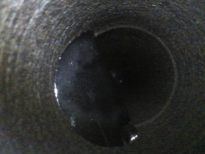
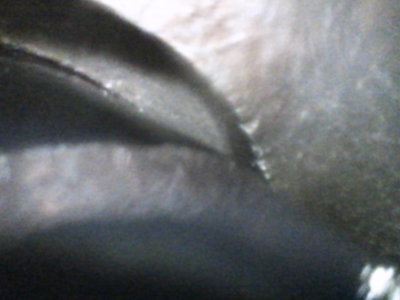
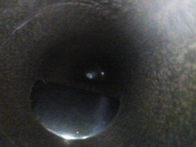
My buddy brought his bore scope over. No issues at the Oil ring. It has lots of room. Exhaust valve has lots of room left at the roller. The intake valve is close. Thankfully it is a smaller base circle billet roller and not a standard base circle cam. If it was then I think I’d have issues. I stuck an .018 feeler gauge under the roller to simulate lash. It don’t have much more till the eyebrow of the lifter at the roller end peaks it’s way into the gallery. Like I say it’s close but will just clear. Checked both sides and it is good on both sides. I figured if I’m doing this I want to be sure it’s gonna work.
Now to get it cleaned up and see if the intake valve will clear at a 104 centerline.

E0287527-DE4D-48BB-B107-64534DC846BF.jpeg 19829D7C-1EE5-413A-A051-63EA61951988.jpeg 3C338DA4-C32E-4666-B197-EBCBE63ED293.jpeg
 
My buddy brought his bore scope over. No issues at the Oil ring. It has lots of room. Exhaust valve has lots of room left at the roller. The intake valve is close. Thankfully it is a smaller base circle billet roller and not a standard base circle cam. If it was then I think I’d have issues. I stuck an .018 feeler gauge under the roller to simulate lash. It don’t have much more till the eyebrow of the lifter at the roller end peaks it’s way into the gallery. Like I say it’s close but will just clear. Checked both sides and it is good on both sides. I figured if I’m doing this I want to be sure it’s gonna work.
Now to get it cleaned up and see if the intake valve will clear at a 104 centerline.

View attachment 591412 View attachment 591413 View attachment 591414
Do a lot of clearances change (grow) when the rpm's reach 6000-7000rpm or even higher when everything starts bouncing around to a certain degree....or do the valve spring operations keep everything "perfect" on clearances ? Just a thought ..
 
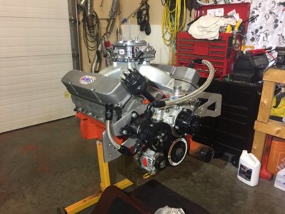
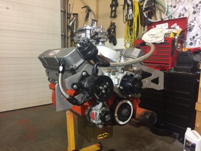
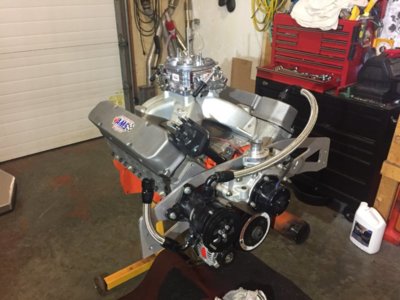
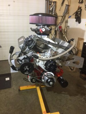
Well it’s back together. Treated the 440 to a new black MSD distributor. Have a few more things to put on yet. Hopefully pushrods show later next week. Goes on the dyno April 23rd.

FE573F79-4BA3-4B24-834D-A19035951677.jpeg 11945DE7-88C5-446A-A994-88234BB598F9.jpeg E7C91125-8FB9-4ACE-BD97-7CCAA787B740.jpeg
 
It won’t make the power the 511 did, but if it goes over 700 on the dyno I’ll be happy for what is in it.
 
What motor plate is that and where did you get it? I’m thinking of putting one in my 69 charger. Thanks
 
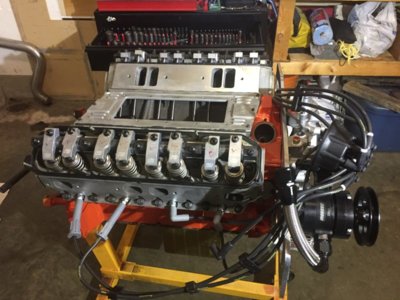
Pushrods showed. Valves set and everything now ready for the dyno. We will see what it does.

9E65A3C5-579A-40FE-89E0-2CD86F220446.jpeg 6E23241E-0531-4B05-9F89-4E0216D91AA0.jpeg
 
Auto Transport Service
Back
Top