• When you click on links to various merchants on this site and make a purchase, this can result in this site earning a commission. Affiliate programs and affiliations include, but are not limited to, the eBay Partner Network.

74 RR Rally Dash HELP

Daves 74

Member
Local time
3:30 AM
Joined
Jun 14, 2020
Messages
18
Reaction score
1
Location
Salem Ohio
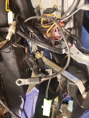
Hello everyone. New to the site. Wanted to know if anyone could give me some advice. There are a few wires near the instrument cluster behind the dash that I can not figure out. Bought wiring diagram and factory wiring manual. Still no clue. Car is a 3 speed manual, 318 ( eventually 440 ). OKAY sooo there are two sets of heavy gauge red and black wires with cooper eyelets. I know that the one set goes to the ammeter. Not sure on the second set. I have a heavier gauge gray wire with a steel eyelet. No clue. There are two blue/white tracer wires with a clip end. No clue where it goes. All these wires are in the same location behind the gauges. I have to say that if you tell me ( It ) goes to a (example)ballast or resistor I probably won't know where it is. Electrical is not a strong point of mine. I can send pictures if needed. Sorry for the long post. Any help is VERY much appreciated. Thanks Dave
 
QUOTE="Nacho-RT74, post: 911589318, member: 11526"]hi and welcome... post the pics please.[/QUOTE]
rt my

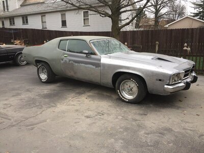
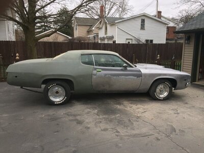
I have an old laptop which does not support my current phone for new pictures the best I can do is load some pictures from a while back. It has since been painted and I, as you have read, am putting it back together.

162.JPG 164.JPG
 
I meant pic of the wires not the car ;).

you can post straight from the phone to the board
 
I meant pic of the wires not the car ;).

you can post straight from the phone to the board
OK, so I am 57 and not very tech savvy. I know how to send to another phone or email address. I was kind of worried when I joined that this might happen. It only makes helping me harder. I may be able to face time, did it accidentally and think I can do it again. Okay, so I am sending them to my wife and she thinks she can get them posted.
 
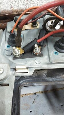
Aren't there two wires on each ammeter post?
 
2 should be black and 2 red.
 
2 should be black and 2 red.
That makes sense to me. Any Ideas about the gray wire with the eyelet? It is a heavier gauge like the red and black ones and has the same type of eyelet but made of something different that copper. And one more, how about the blue/ white tracer . they are a smaller gauge and the two wires go to one clip. All the wires are about the same length and attach somewhere in that general area. THANK YOU for the help so far.
 
The red and black wires yes could be in that way, but that’s not stock, unless somebody modified the charging wires ( like the parallel path I allways promote to save the bulkhead ) or got from factory a 65 amps alternator ( should be coded )

the gray wire could be some high amp accesory, such the rear glass heater ( the grilled glass not the blower which it was a brand new option for 74 ) or power windows. Will need to check the diagram. But I was interested on check the wires to know if they are original or not.

IF the rear glass heater is the grill kind and the car got it, the extra ammeter wiring it could be logical along with the 65 amps alternator

Same to the blue wires mentioned! Could be for the seatbelt light, but preffer to check the “clip” he mentions.
 
Last edited:
If the blue wires get a plug ( “clip” ) like this

1462819-40.jpg


It is the seatbelt light on panel above the cluster. You should have the male and female around to be connected.
 
just checked the diagram and heater glass wire should be black. And per diagram there is no gray wire arriving to amm studs
 
Yes the car has rear defrost. I will take a picture of the blue wires clip along with gray wire and post when I get home from work. Thanks for the help so far! Feel like I am finally making progress.
 
On 74 there was two kind of rear defrost, the blower kind and the grill kind heating elements over the glass. This last should get the indicator light somewhere ( never have seen the full setup on a car so can’t say where should be )

74_Satellite_11.jpg
 
Okay,
On 74 there was two kind of rear defrost, the blower kind and the grill kind heating elements over the glass. This last should get the indicator light somewhere ( never have seen the full setup on a car so can’t say where should be )

View attachment 963667
On 74 there was two kind of rear defrost, the blower kind and the grill kind heating elements over the glass. This last should get the indicator light somewhere ( never have seen the full setup on a car so can’t say where should be )

View attachment 963667

20200615_165156.jpg 20200615_165137.jpg 20200615_165112.jpg 20200615_165047.jpg 20200615_165032.jpg 20200615_164942.jpg 20200615_164853.jpg
 
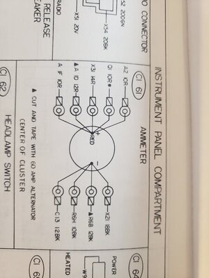
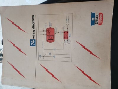
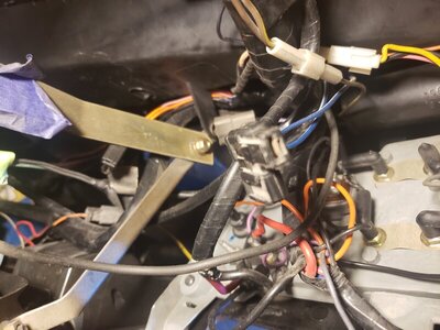
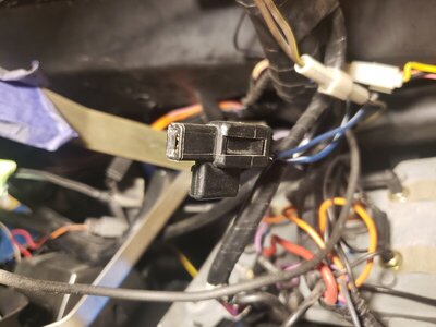
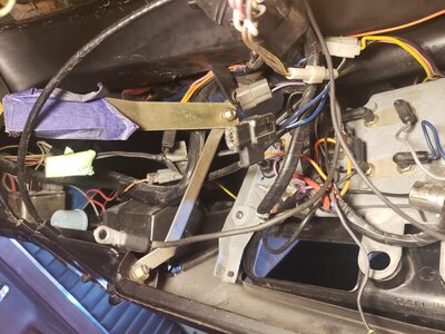
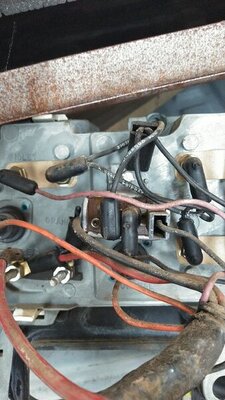
Okay, we figured out how to get the pictures in. The first two pictures are of the wiring manual I tried to use. If you look at the AMMETER diagram, to me, it looks like multiple wires "could" go to it. ??? The next three pictures are of the wires. The sixth picture is of a possible location for the blue with white tracer. I just did not want to put a wire where it " may " go. The last picture shows the " gray " wire, which may appear to be black to some???? Also, I hooked the second red and black wires to the ammeter but looking at the wiring diagram, they say to cut and tape. I hope you guys can understand the issues I am having. Thanks again
 
This is an org not messed with 73 with a tac so Same configuration.
I believe the second big red wire was a lead for the power windows

KIMG0710.JPG KIMG0711.JPG
 
ok that wire is black not gray is actually black... should go into the bunch of black ammeter wires.

I see that blue "clip". Thats a dual male/female packard 56 terminal used to make a "splice" or bypass to make a chain of connectors. I only had seen that plug used to the iddle stop solenoid at carb. That plug could be very well also related to the rear glass defroster. I never have sen personally the rear glass defroster system but on diagram shows a blue wire used on circuit, mostly sure to make the system just to work when car is in RUN ( blue wiring system is related to the RUN circuit ). Id like to see that system personally someday... where is the switch ( I guess down the dash similar to the blower kind defroster switch ) the pilot light etc...

SOMEWHERE into the underdash harness ( mostly sure close to the brake pedal switch ) you must have hanging around a blue wire with a female packard plug to conect it here. It used to be used when you got the electric trunk release system too.

since you have the diagram book for 74 ( which is not easy to read like earliers ) check on the legend page the conector CI64... this conector is shown on 21th sheet of the 74 diagram ( line G5 20DBL*... which means is blue traced white wire )... coordenates 82 B. It could be very well that plug.

I don't have the legend page with me to check it myself, just the diagrams scanned... my Factory service manual with the diagrams is in Venezuela with my car and I'm in Spain at this moment.

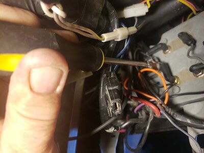
the device you are pointing out with the screwdriver is the voltage limiter. The U shaped prong setup gets a black wire to give the input signal and also gets a noise supressor condenser.

s-l1600.jpg


About the "cut and tape deal"... will dig deeper into that because I know why it says that ( already analized that ) Basically is because the bulkhead conections were bypassed when using a 65 amps alternator, being the ammeter wired with wires coming from firewall with a grommet ( bulkhead conections are weak to hold the load of some accesories like the electric glass defroster ), but will find the way to explain this wiring to you better. Is late now for me.
 
Last edited:
I see it does not have a second black also attached?? The possibilities appear to be growing. As always, Thanks for the help


as mentioned, the voltage limiter ( which gets down the 12 volts signal to 5 volts signal to feed the gauges ) gets 3 wires... one input coming from dash harness, one output spreading the power to the gauges and the noise supressor condenser which conects to the U shaped terminal on limiter, just like the input wire

868-0XX(mech)-3.jpg
 
OK... just detailed better the pic of the blue wires conection... you don't have nothing to do with it... the defroster blue wire ( mostly sure the CI64 as I mentioned ) is already conected to the dash harness plug on back of the dual plug. The female end in front is left open just to conect any other accesory requiring same RUN circuit signal if equipped. If you for example had an electric trunk release sistem or power windows will conect to that end... but since you don't, will remain open. Don't worry about it.

If you didn't have the defroster or the electric trunk release system or any other accesory requiring the run circuit signal, the single female plug also with the blue wire ( the one conected on back of the CI64 ) will be also unused hanging around
 
Last edited:
Auto Transport Service
Back
Top