• When you click on links to various merchants on this site and make a purchase, this can result in this site earning a commission. Affiliate programs and affiliations include, but are not limited to, the eBay Partner Network.

74 RR Rally Dash HELP

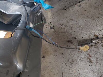
ok that wire is black not gray is actually black... should go into the bunch of black ammeter wires.

I see that blue "clip". Thats a dual male/female packard 56 terminal used to make a "splice" or bypass to make a chain of connectors. I only had seen that plug used to the iddle stop solenoid at carb. That plug could be very well also related to the rear glass defroster. I never have sen personally the rear glass defroster system but on diagram shows a blue wire used on circuit, mostly sure to make the system just to work when car is in RUN ( blue wiring system is related to the RUN circuit ). Id like to see that system personally someday... where is the switch ( I guess down the dash similar to the blower kind defroster switch ) the pilot light etc...

SOMEWHERE into the underdash harness ( mostly sure close to the brake pedal switch ) you must have hanging around a blue wire with a female packard plug to conect it here. It used to be used when you got the electric trunk release system too.

since you have the diagram book for 74 ( which is not easy to read like earliers ) check on the legend page the conector CI64... this conector is shown on 21th sheet of the 74 diagram ( line G5 20DBL*... which means is blue traced white wire )... coordenates 82 B. It could be very well that plug.

I don't have the legend page with me to check it myself, just the diagrams scanned... my Factory service manual with the diagrams is in Venezuela with my car and I'm in Spain at this moment.

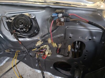
the device you are pointing out with the screwdriver is the voltage limiter. The U shaped prong setup gets a black wire to give the input signal and also gets a noise supressor condenser.

View attachment 963713

About the "cut and tape deal"... will dig deeper into that because I know why it says that ( already analized that ) Basically is because the bulkhead conections were bypassed when using a 65 amps alternator, being the ammeter wired with wires coming from firewall with a grommet ( bulkhead conections are weak to hold the load of some accesories like the electric glass defroster ), but will find the way to explain this wiring to you better. Is late now for me.
OK, I will look into some of the things you pointed out. The rear defrost switch is mounted under the dash to the left side of the steering column. If you are ever in Ohio near Youngstown, Cleveland, or Pittsburgh, we can make that happen with pleasure. A couple of other different things about the car, 3/4 vinyl roof, 3 speed manual, console, and the rare rocker moldings. Thank you for your time and effort.
 
OK... just detailed better the pic of the blue wires conection... you don't have nothing to do with it... the defroster blue wire ( mostly sure the CI64 as I mentioned ) is already conected to the dash harness plug on back of the dual plug. The female end in front is left open just to conect any other accesory requiring same RUN circuit signal if equipped. If you for example had an electric trunk release sistem or power windows will conect to that end... but since you don't, will remain open. Don't worry about it.

If you didn't have the defroster or the electric trunk release system or any other accesory requiring the run circuit signal, the single female plug also with the blue wire ( the one conected on back of the CI64 ) will be also unused hanging around
So you are telling me just tape it up and forget about it. Ok So the second black wire with the eyelet also goes to the ammeter. OK I have looked over the second set of black and red wires with the eyelets and they do go through a grommet on the fire wall and have white plugs clips on the ends. I will look over my photos of the engine compartment tomorrow and let you know what I find. I did take a lot of pictures of the car, just none of the dash wiring. Go figure.
 
Last edited:
No need to tape the blue wire conector. Just leave it like it is. It must be just like that hanging around.
 
Last edited:
No need to tape the blue wire conector. Just leave it like it is. It must be just like that handing around.
First, I just realized where you are from so I am guessing you won’t be in my area anytime soon. My offer still stands if you ever are. Second, I am impressed with your knowledge and library of information especially for not being in the states. Okay, wanted to make sure I am following you correctly. Blue/white tracer leave alone. The wire I thought might have been gray with the eyelet, which is really black, gets attached to the ammeter. Now, I will check my 318 motor and see if it has the 65 amp alternator. If it is, do I hook up both sets of black and red wires, or just the ones coming through the grommet, not the fuse box. My last question, a few pictures above showing the voltage reducer with wires attached, shows the far right wire as being black. I have the same style clip, square brown color, but my wire is gray. I have no other wires left to go to that terminal. Do you think this is the correct wire. We are almost there. Thank you. JUST LOOKED: It is a 65 AMP Alternator
 
Last edited:
Well I have been in USA once, going to Carlisle 2008 and I'd like to go again someday soon.

I'm actually impressed you didn't noticed I wasn't from USA since my english is just good enough but not really perfect.

About what I know of these cars. I have a 74 Charger assembled in Venezuela ( yes Chrysler got several assembly plants overseas ) and we got in Venezuela some good cars from northamerica i.e. 71/74 Chargers. They were same body and look ( not like Brazilian or Australian Chargers ) but quite different equipment options. So even my car was ALLMOST a 74 Charger Rallye ( but standard cluster, lack of rear sway bar, plus the restoration parts... ), I wanted a full real Charger Rallye like the ones in USA, so I had to get documented to find the right parts because making it wrong I would pay more on shipping being international customer, which it means mistakes are more expensive for me LOL. Since I couldn't make a mistake then it has taken me some years but finally made it.

Then I had to learn to make stuff by myself on my car because I noticed how many A$$ho1es I had around me which pretended to call themself as "mechanic".

Now:
Blue white tracer, correct, leave it alone.

Ammeter wires. The correct ones should be the ones coming through the grommet as far the oposite end on engine bay is conected too. The other ones are part of the underdash harness and underdash harness is the same for all 74 B bodies with Rallye cluster and depending of the buildsheet some extra harnesses were attached or not, or some wires used or not. HOWEVER I know PART of the underdash charging circuit is still used to feed the main circuit splice ( which is still down the tape ), but I have a technical problem right now with my laptop, screen turns on and suddenly goes off, a problem aparently with the backlite so I can't see anything on the screen to check the diagram right now. This problem is being random and maybe tomorrow will work again! So going to bed and will hope tomorrow will be able to check the diagram. I KNOW how it works the system because I added those extra paths with a grommet on my car, but was a personal upgrade job not being stricted to the diagram. Being a factory setup on your car I would preffer try to guide you on the factory setup correctly. AS FAR I RECALL you should get an extra wire with a fuse link ( different to the one used on starter relay attached to the red wire ) to feed the black wire on cavity 18 WHICH was intended to be the alternator wire on cars without those extra red and black paths when 65 amps alternator was equipped, leaving then the underdash harness eyelet ends red and black wires unnecesary to be used ( hence the reason diagram could say "cut and tape" but you don't need to cut, but in any case just isolated ) ... HOWEVER let me be sure after check the diagram with detail. This setup was changed between 71/74 models and I don't have everything in my mind right now.

Voltage limiter gets two black wires one with a wider female end what conects to the voltage limiter bracket prong, which a ground reinforcement. Then there is another one with female end on regular size which conects to the same U shaped terminal the noise suppression condenser and the pics posted previously and is an ACC positive source. This size difference was made intentionally to make imposible to switch them around and get a short conecting the positive wire into the wider ground prong on bracket.

The extra black wire with eyelet terminal, should be as mentioned the heater power source, so should be attached to the same "black" side of the ammeter.

I can't recall the gray wire you are mentioning right now. Black plug or brown plug could be anything but a stock difference on assembly plant? Dunno...
 
Last edited:
( sorry, edited several times the previous post making some corrections after read it couple of times... tipical on me LOL )
 
Well I have been in USA once, going to Carlisle 2008 and I'd like to go again someday soon.

I'm actually impressed you didn't noticed I wasn't from USA since my english is just good enough but not really perfect.

About what I know of these cars. I have a 74 Charger assembled in Venezuela ( yes Chrysler got several assembly plants overseas ) and we got in Venezuela some good cars from northamerica i.e. 71/74 Chargers. They were same body and look ( not like Brazilian or Australian Chargers ) but quite different equipment options. So even my car was ALLMOST a 74 Charger Rallye ( but standard cluster, lack of rear sway bar, plus the restoration parts... ), I wanted a full real Charger Rallye like the ones in USA, so I had to get documented to find the right parts because making it wrong I would pay more on shipping being international customer, which it means mistakes are more expensive for me LOL. Since I couldn't make a mistake then it has taken me some years but finally made it.

Then I had to learn to make stuff by myself on my car because I noticed how many A$$ho1es I had around me which pretended to call themself as "mechanic".

Now:
Blue white tracer, correct, leave it alone.

Ammeter wires. The correct ones should be the ones coming through the grommet as far the oposite end on engine bay is conected too. The other ones are part of the underdash harness and underdash harness is the same for all 74 B bodies with Rallye cluster and depending of the buildsheet some extra harnesses were attached or not, or some wires used or not. HOWEVER I know PART of the underdash charging circuit is still used to feed the main circuit splice ( which is still down the tape ), but I have a technical problem right now with my laptop, screen turns on and suddenly goes off, a problem aparently with the backlite so I can't see anything on the screen to check the diagram right now. This problem is being random and maybe tomorrow will work again! So going to bed and will hope tomorrow will be able to check the diagram. I KNOW how it works the system because I added those extra paths with a grommet on my car, but was a personal upgrade job not being stricted to the diagram. Being a factory setup on your car I would preffer try to guide you on the factory setup correctly. AS FAR I RECALL you should get an extra wire with a fuse link ( different to the one used on starter relay attached to the red wire ) to feed the black wire on cavity 18 WHICH was intended to be the alternator wire on cars without those extra red and black paths when 65 amps alternator was equipped, leaving then the underdash harness eyelet ends red and black wires unnecesary to be used ( hence the reason diagram could say "cut and tape" but you don't need to cut, but in any case just isolated ) ... HOWEVER let me be sure after check the diagram with detail. This setup was changed between 71/74 models and I don't have everything in my mind right now.

Voltage limiter gets two black wires one with a wider female end what conects to the voltage limiter bracket prong, which a ground reinforcement. Then there is another one with female end on regular size which conects to the same U shaped terminal the noise suppression condenser and the pics posted previously and is an ACC positive source. This size difference was made intentionally to make imposible to switch them around and get a short conecting the positive wire into the wider ground prong on bracket.

The extra black wire with eyelet terminal, should be as mentioned the heater power source, so should be attached to the same "black" side of the ammeter.

I can't recall the gray wire you are mentioning right now. Black plug or brown plug could be anything but a stock difference on assembly plant? Dunno...
 
You have been very helpful and patient. I think the gray wire could go for a clock, if the car had one. That is what I though originally, but started looking for a wire, any wire, to put on the far right side of the U shapes flat post. You have no idea how much your help means. I have been waiting for months to figure this out buying anything I though would finish this. I am an engineer, but you wouldn't think so because you have to spoon feed the information ( slow and simple ). THANK YOU and I will wait to hear from you again. Just looked, the heaviest black wire coming out of the fuse box located in the engine compartment has a fuse link attached to it, if that is the wire you were talking about.
 
Clock wire on rallye cluster is feeded by a small gauge black wire betweem amm post and clock, and if there is not clock, then you don't get that wire

IMG_1078.jpg
 
This is what a regular car wiring would be

Main charging wires-system.jpg


So as a standard setup, this is the standard configuration harness for the charging network.


Ok this is what the diagram shows me for 65 amps, just like I described above and I remembered

65 amps wiring.jpg


Dunno if your forward lighting harness got the red wire coming from the cavity 16 ( the one offset on diagram ), and if it got it is going somewhere or is just hanging around so I decided not include it into the diagram. The standard set up would get a red 12 gauge there

The cab side of the wires coming from bulkhead ( taped with the rest of wiring harness ) which should be 12 gauge shouldn't be conected because if you do, those lines would be out of the fuse link protection. Actually the diagram doesn't show if or if does or if doesn't need to be conected, but my logical says it doesn't. ( actually still if you conect the red one with eyelet could arrive to nowhere into the engine bay side if you don't have that section on forward lighting harness or even the fuse link for it )

I don't know if your engine harness got two black wires arriving to alternator stud, one 8 gauge and one 12 gauge. As mentioned I actually never have seen the original wiring system of a factory 65 amps alternator and I made my own personalized setup based on that parallel path. If it does, the 12 gauge wouldn't need to be used, because as you can see on next diagram would actually arrive to the 18 cavity of the regular ( non 65 amps ) wiring system. Or maybe both wires are into the alternator stud, but a 12 gauge wire could be cut and taped on the end arriving to the bulkhead conector, because the blue fuse link ( 16 gauge ) conected to a 10 gauge black line coming out from the splice point at 8 gauge wire will be covering that. This line is the one what feeds everything on car.

at starter relay, the standard charging system would get a 16 gauge fuse link ( blue ) but on 65 amps alternaotr cars, the fuse link is increased to 14 gauge being red traced ( dunno if white trace or black trace, but doesn't matter )
 
Last edited:
just to be more "graphic" on the idea I mentioned on previous reply... MAYBE you find this... standard wiring setup mixed with the 65 amps wiring setup added, but with the required mods made on assembly line

65 amps wiring1.jpg
 
Last edited:
Gray wire... if your car got tach ( with it seem it does ) the gray wire goes to a prong on tach. That wire should arrive to the cavity 4 on bulkhead conector ( same than the Transmission harness section )
 
rear defog switch looks like an air grabber or, tailgate window switch and mounts lower left where there are three mount locations.
 
Yes I know, I have the rear defog blower kind which gets two blower speeds... but I had forgot how it was the rear defog with electric element on glass system and I just remembered around 2 years ago I already had talked about this on another board. These also get a pilot light attached to bezel which it was my main concern and is just on and off...

index.php?action=dlattach;topic=131310.jpg


index.php?action=dlattach;topic=131310.jpg
 
Last edited:
I am going to look into everything you have given me. I then will take a couple of pictures of the engine compartment wiring for you to look over. Please give me a day or so. Wifey wants a few things done. Happy wife, happy MOPAR life.
 
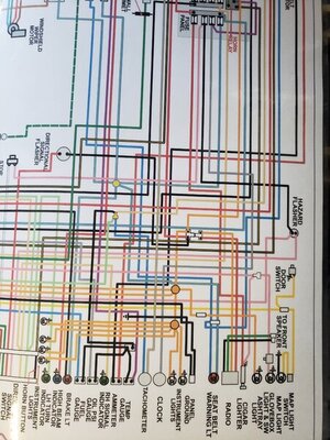
Hello again. I have taken a few more photos. The first picture is of one of the wiring diagrams that I have. If you look at the clock area, it is showing a gray wire coming from the fuse box to the clock?? The diagram is for a rally dash. No big deal either way. The next pictures are how my wires are in the engine compartment. Notice the two fuse links coming out of the starter solenoid?? So, my questions are 1. If I follow the diagram you show, I should not use the red and black wires from the fuse box, only the ones from grommet. This will also leave the extra fuse link not being used. 2. I should only attach the red and black coming from the grommet, along with second black wire with the steel eyelet. Let me know what you think. As always. Thank you

20200618_194126.jpg 20200618_194040.jpg 20200618_194015.jpg 20200617_200800.jpg
 
Ok we have really interesting stuff here.

About the gray wire for clock, as mentioned SUPOSSELLY there is no gray wire to clock on Rallye cluster, but a direct jumper wire between ammeter post and clock. However Standard cluster got them.

Do you have tach ? tach gets a gray wire coming from - lead of coil, along with blue one for power source.

I must say I don't have any gray wire for clock and is an USA harness from 74

now we have MORE interesting stuff here.

I can see you got TWO fuse links on starter relay... those will hook up into both red wires. Red wire from grommet into the red fuse link and red wire from forward lighting harness into the blue fuse link. Weird they duplicate this network but if those are there I guess should be conected.

Black wire coming from grommet will plug on black wire on engine harness. now...wondering if you have THIS on yellow circle... pic is not clear enough

65 amps wiring2.jpg


and what's this I'm pointing out with the orange arrow ?... that could be part of the section I'm circling yellow on diagram, which is a splice from the main alternator wire accidentally inserted between engine harness and forward lighting harnesss

20200618_194015.jpg


on a side... you'll need to isolate these terminals to save from a failure or even a short around. These are the alt field wires and needs to be protected from everything around.

20200618_194040.jpg


they should look like these once conected on back of alt:

dartwiring001.jpg


you could replace those terminals and use the correct Packard 56 terminals and plug setup, or simply cover those with shrinking tube to get them safe from everything around
 
Last edited:
You have everything right. I have a gray and blue wire going to the tach. I also do have the blue wire link you circled in the diagram. So, not sure of the gray wire but I do not think it is a big deal. Okay, last two questions, 1. does the ammeter get only the two wires ( red/black) coming from the grommet through the fire wall along with the black with steel eyelet for the defrost? 2. And should there only be two wires going to the voltage drop/ noise suppressor? There are no more wires left to put there. Would you take a token of my appreciation in the form of a payment? PayPal??? AND, can I come to you for further questions or advice. I see the light at the end of the tunnel and you got me there. Also, is there anything over here that you are still looking for for your Charger??? NICE CAR
 
well, since you have both sets of red wires running to fuse links on starter relay AND you have ( althought I can't see it on your picture, but per what you said ) the link runing on the other black line to the engine haress bulkhead plug, I'd say to conect everything like this:

65 amps wiring1A.jpg


Actually although I made it similar on my own car, later I analized and doesn't have to much sense have a dual fuse link on starter relay from the RED circuit coming from ammeter, because that will make to take too long to blown them out if a short appears ( I will modify that on my own car ). Neither have sense to have a fuse link on the black wire through the bulkhead to protect the circuits to the main splice into the cab if at the end the thick wire with the grommet will be still feeding the main splice is a short comes on. But if the car came with them is to use those, so wire them like factory did ( 74 diagram doesn't specify about cut and tape them, althought earliers do )

The other black wire we are assuming is the power to the heater relay ( wherever it is the relay, which I dunno ) is to conect it on the same bunch of black wires into the amm stud. All the amm stud wires will need to be clean and tight. I guess the black wire have a 20 amps in line fuse ( diagrams shows it ) somewhere.

Ok so you have the tach wires in place. So I have NO IDEA what could be the gray wire you got. Unless is some splice made by the last owner, some mod but by now is something I still don't know. I'm trying to imagine on some extra equipment I never have known on these cars carrying a gray wire.

Could be the gray wire the one to the VL limiter ? have no idea, should be black.... maybe it was spliced and got enlarged with this gray wire ? dunno. The Volt limiter wire gets sourced from ACC circuit. If you want to test it somehow?... you could check for continuity between that wire and the ACC provision on bottom of fuse box ( just right below the fuses row ). It should get continuity just with key in ACC ( or RUN )


Voltage limiter must get 4 black wires like the pic posted by Bb70charger500 and each one is imposible to mix them up ( althought +12 volts wire and condenser can be reversed they are conected to the same provision ). +12 volts, ground, output to gauges and condenser
891849-fa0459e2c6a72a6afbaf7c917390b1bc.jpg


ALTHOUGHT the system can work without the condenser since is just a noise suppressor, and ground wire could be disconected because as far cluster is correctly attached to dash and Voltage limiter is tight againts the cluster, the limiter and the gauges could work ( but for safety better to have that ground wire attached, because the absence of good ground there, can burnt the gauges )

Payment... God... a real temptation and a good help at this moment, but no, don't worry, is a pleasure to me.

Searching parts for my Charger ?... I'm allways hunting for parts but my car is at this moment dissasembled over jackstands and being painted. Dunno if when reassembling will find something missed or broken ( I HOPE NOT!!!! ). I guess If I need something will start a WTB thread LOL.
 
Last edited:
Well you have another friend in the states now. It has truly been a pleasure and an education. I will continue to check this site every so often. The payment offer always stands. Keep that in mind. You earned it. Let me know how and it will happen. Good luck on the car. Thank You Dave
 
Auto Transport Service
Back
Top