The #10 red wire from the positive battery post to the starter relay on a 1969 B-body. Isn't this wire hot all the time and allows the alternator to recharge the battery?BTW, that wire keeps hot just while cranking... so why move the fuse link from its original location ?
You are using an out of date browser. It may not display this or other websites correctly.
You should upgrade or use an alternative browser.
You should upgrade or use an alternative browser.
Ammeter to Voltmeter Conversion -- Existing Wire Question
- Thread starter mrmolding
- Start date
Jeff Erwin
Well-Known Member
Is CrackedBack still making the headlight relay harnesses? I tried to PM, his boxes are full. Need one for a 71 SuperBee.
- Local time
- 9:30 AM
- Joined
- Jan 14, 2009
- Messages
- 2,297
- Reaction score
- 1,925
- Location
- Shoreline, Washington
So then, on a correctly loaded (no aftermarket loads connected directly to the battery or starter relay), well maintained original charging circuit, it’s the 0 to at most a few amps of battery charging current flowing through the ammeter while the vehicle is in normal operation that poses the greatest danger? Does that really make any sense? With such a design flaw, would have thought all Chrysler built passenger vehicles from ‘60-70s would surely have burned to the ground by now, or I would have seen at least one example of this back in the day at the dealers. Note: excluding the late-seventies truck plastic framed ammeters, saw plenty of those.By connecting both the red and black wire to one stud on the ammeter, you are eliminating the ammeter from the circuit. Same thing as just bolting the 2 wires together and insulating the connector.
All my cars, past and present, have/have had fully functional ammeters, 100–150-amp alternators, 8ga charge circuit wiring by-passing the bulkhead connections, all running several various high current aftermarket accessories (connected on the alternator side of the ammeter as was/is intended by the original design). Don’t fear the “0” reading on the ammeter at all.
Last edited:
Nacho-RT74
Well-Known Member
The #10 red wire from the positive battery post to the starter relay on a 1969 B-body. Isn't this wire hot all the time and allows the alternator to recharge the battery?
yes, and not just on 69 B bodies but all cars but the same is happening on the original fuse location between starter relay and bulkhead. The only difference locating the fuse link between starter relay and batt is the extra load to feed the starter motor solenoid, which shouldn't be fused and the solenoid wire IS THE WIRE which is only hot while cranking. An incorrect rate fuse link on batt side of the starter relay could blown the fuse by the solenoid load when cranking...
or backwards, an oversize fuse on that section to allow the load for the starter motor solenoid won't protect at all a short to ground anywhere on the car, burning everything before the fuse blows
so... why relocate the fuse link, maxifuse or whichever protection choosen between starter relay and batt ? The stock location on bulkhead/firewall side is the right one.
Last edited:
Nacho-RT74
Well-Known Member
Don’t fear the “0” reading on the ammeter at all.
which is the perfect, correct and desired status, as far everything is correctly sourced on alt side of the charging system as you mentioned.

as posted many times:
Last edited:
Nacho-RT74
Well-Known Member
Looking at the wiring diagram on Post # 7, the red wire appears to be a redundant parallel circuit. The red and black wires are terminated together under the dash, and again at the starter relay. For simplicity's sake, could this red wire be eliminated altogether as it is no longer needed to complete the ammeter circuit? Am I missing something here? Per another post, I now realize that terminating both wires on an ammeter post is not a good idea, so I will not be doing that.
Even as many members here knows I'm not agreed with this mod, the redundant ( parallel ) wire is helping to support more load through the existant wires. Would be the same removing completelly both wires and splicing one thicker wire between fuse link and straight to the main splice into the cab. However that would need to get deeper into the harness. Diagram is showing a simple way to use what you get on your car.
I make the same reduntant wiring running to ammeter on both sides to save the bulkhead weak point. There are many ways to cook a pork. 72RoadrunnerGTX get his own prefferences, I get mines, some other get their own preferences. Everything is fine as far you really know what you are doing.
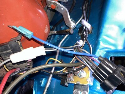
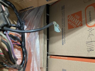
You guys are all fantastic with your responses! Thanks so much again! But I have a related question in regard to the stock engine harness vs the M&H harness. I'm replacing all of the harnesses and the Fuse link Wire on the new M&H engine harness seems to have a smaller diameter of the original one. Maybe like 10ga to 16ga (estimates). Does that mean (forgive me not an electronics guy) that the new M&H is "safer" since it will blow sooner? Black link is original, blue is new in M&H harness.
Update: I think I found my answer in the service manual. It lists the fuse link gauge as 16 like the replacement harness. Not sure why thicker. So...nevermind.


Update: I think I found my answer in the service manual. It lists the fuse link gauge as 16 like the replacement harness. Not sure why thicker. So...nevermind.


Last edited:
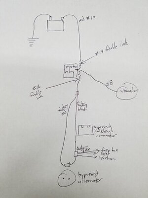
I think you are talking about leaving the factory wiring and #16 fusible link in place. This drawing is what I am referring to. No fuse link on the #8 wire around alternator to start relay, #14 fuse link added to the factory small red battery to start relay, and a #16 fusible link in the cars wiring circuit with the bulkhead and ammeter bypasses. My question being, is this safe, or would it be better to eliminate the #14 link and instead add a #12 fusible link in the alternator wire?yes, and not just on 69 B bodies but all cars but the same is happening on the original fuse location between starter relay and bulkhead. The only difference locating the fuse link between starter relay and batt is the extra load to feed the starter motor solenoid, which shouldn't be fused and the solenoid wire IS THE WIRE which is only hot while cranking. An incorrect rate fuse link on batt side of the starter relay could blown the fuse by the solenoid load when cranking...
or backwards, an oversize fuse on that section to allow the load for the starter motor solenoid won't protect at all a short to ground anywhere on the car, burning everything before the fuse blows
so... why relocate the fuse link, maxifuse or whichever protection choosen between starter relay and batt ? The stock location on bulkhead/firewall side is the right one.

Dave6T4
Well-Known Member
- Local time
- 12:30 PM
- Joined
- Dec 31, 2020
- Messages
- 9,176
- Reaction score
- 22,071
- Location
- Ontario, Canada
I have already gotten into the factory harnesses and replaced the alternator circuits with 8 ga. wire and passed it through the firewall via grommeted holes, bypassing the stock bulkhead connector. Since I am no longer using the stock smaller gauge wire, would I be able to safely remove the redundant red wire, which is also 8 ga.?Even as many members here knows I'm not agreed with this mod, the redundant ( parallel ) wire is helping to support more load through the existant wires. Would be the same removing completelly both wires and splicing one thicker wire between fuse link and straight to the main splice into the cab. However that would need to get deeper into the harness. Diagram is showing a simple way to use what you get on your car.
I make the same reduntant wiring running to ammeter on both sides to save the bulkhead weak point. There are many ways to cook a pork. 72RoadrunnerGTX get his own prefferences, I get mines, some other get their own preferences. Everything is fine as far you really know what you are doing.
VitaminCRR
Well-Known Member
So I've been looking for an answer to a question and this seems like a likely place to ask it. If I run a #6/8 wire from the alternator to the starter relay do I splice it in to the harness somewhere or do I just run an additional wire from the alt to relay? I have a 2 or 3 wire harness coming out of the alt. Does this harness stay and I run the wire on top of it? Am I making sense?
Nacho-RT74
Well-Known Member
I think you are talking about leaving the factory wiring and #16 fusible link in place. This drawing is what I am referring to. No fuse link on the #8 wire around alternator to start relay, #14 fuse link added to the factory small red battery to start relay, and a #16 fusible link in the cars wiring circuit with the bulkhead and ammeter bypasses. My question being, is this safe, or would it be better to eliminate the #14 link and instead add a #12 fusible link in the alternator wire?
View attachment 1175081
Yes, I thought you were relocating/replacing the existant stock fuse link With a new one just on batt side of the starter relay. According to that diagram I'd add it into the alternator wire attached to the starter relay. Starter motor circuit must be free of any circuit protection. "That's just my opinion of course".
Last edited:
Nacho-RT74
Well-Known Member
I have already gotten into the factory harnesses and replaced the alternator circuits with 8 ga. wire and passed it through the firewall via grommeted holes, bypassing the stock bulkhead connector. Since I am no longer using the stock smaller gauge wire, would I be able to safely remove the redundant red wire, which is also 8 ga.?
Still not really sure on the full job you made to give you my opinion of course
Nacho-RT74
Well-Known Member
So I've been looking for an answer to a question and this seems like a likely place to ask it. If I run a #6/8 wire from the alternator to the starter relay do I splice it in to the harness somewhere or do I just run an additional wire from the alt to relay? I have a 2 or 3 wire harness coming out of the alt. Does this harness stay and I run the wire on top of it? Am I making sense?
This deserves a longer and detailed answer with a diagram, but is late in Spain right now to sit on my PC and "give my opinion of course". If you have the patiente I can provide my thoughts on your question in about 20 hours starting now...
Nacho-RT74
Well-Known Member
Sorry... I got home later than expected and too tired. Will try tomorrow
Found this article — answers my question about a charge wire and recommended size based on alternator amps.
https://www.allpar.com/threads/taki...ep-your-mopar-current.237043/#post-1085245456
https://www.allpar.com/threads/taki...ep-your-mopar-current.237043/#post-1085245456
Nacho-RT74
Well-Known Member
****! I have failed you... but is just because I want to sit in front my pc and making it calmed down...
****! I have failed you... but is just because I want to sit in front my pc and making it calmed down...
No rush! Restoring the heater box and waiting for heater core resto parts.
Nacho-RT74
Well-Known Member
Found this article — answers my question about a charge wire and recommended size based on alternator amps.
https://www.allpar.com/threads/taki...ep-your-mopar-current.237043/#post-1085245456
yes,. but no... I mean, no matter the alt output capacity, more than the car accesories demanding load. You will find the same alternator or batt is feeding a bulb with a 18 gauge wire, than the A/C-Heater Blower with a 14 gauge wire, or Ign switch with 12 gauge wire. So more than the source itself is the device to be sourced.
We can see it in fact on the wire to feed the starter motor being 4 or 2 gauge and the wire to feed the cab on10 gauge up to the starter relay, then becomes into 12 through a 16 fuse link ( Starter relay splices the load to the starter SOL with a 10 gauge wire ), and everything from the same batt. So you can find a 500, 600, 700 amps batt feeding the cab with a 12 gauge wire at the end!!!
SURE you must meet all the inputs requirements on the wire coming from the ouput source, but doesn't mean it MUST be the full alternator o batt load capacity to source.
is not the same the load able to source, than the load needed to be sourced. Remember amperes are not pushed in by the source but pulled/sucked out by the device/accesory
Last edited:
Nacho-RT74
Well-Known Member
So I've been looking for an answer to a question and this seems like a likely place to ask it. If I run a #6/8 wire from the alternator to the starter relay do I splice it in to the harness somewhere or do I just run an additional wire from the alt to relay? I have a 2 or 3 wire harness coming out of the alt. Does this harness stay and I run the wire on top of it? Am I making sense?
Ok, let´s try to beging with this. You say got 3 wires running out from the alt stud but where are they going ?
the main and stock circuit is this one ( despite bulkhead cavities they are E and 71/74 B body based )
If you make this up to starter relay stud ( or batt post ), you are "virtually" bypassing the ammeter, because even being allmost unapreciable really close to 0, the ammeter represent still a tiny resistance to the system, more than the rest of terminals. So same as the water, the load will run for the easier paths available to reach the load demand. The stock red wire could still hand a small amount of load but maybe not even able to move enough the ammeter. Maybe couple of amps ? dunno. It will depend on the total resistence of the new path against what represents the amm resistance itself.
On this stage, the bulkhead paths same as the ammeter are being free from the load required to recharge the batt when it gets discharged ( arrows on VIOLET CIRCUIT wire would be on the oposite direction but same proportion related to the load to handle to recharge the batt being outside the stock system ), and the load required by the main splice inside the cab ( down the harness tape ) is somehow being shared, so the bulkhead keeps somehow safer.
All in all, the wire between alt and batt/starter relay stud what makes is become ALL the Charging system in a giant junction network, where the loads will go throught the easier path available to reach the power need, which obviouslly usually is not the ammeter path, unless the other paths resistances are closer to the ammeter resistance ( bad condition wiring, terminals, or not enough gauge on the rest of wiring paths to the load required )
NOW, if you have several wires attached to the alt stud but NO ONE OF THEM is linked to the batt or starter relay stud which would mean you will be passing throught the ammeter circuit whne engine is off, you are simply using the alt stud just like a junction point or power buss... power either coming straight from alt if alt is being enough to feed everything hooked up to the alt circuit... or if alt is not enough, the required power to feed the alt unneficiency, coming from bat THROUGHT the ammeter circuit. WHICH BTW IS THE CORRECT WAY TO MAKE IT... but the alt MUST be upgraded to feed any extra accesory, to keep safe the ammeter and the bulkhead connections.
the only difference on this last diagram between both splices or junctions where get the power, is the load being handled by the bulkhead ( and stock 12 gauge wire alt wire ) depending if coming most of them from inside the cab or coming from the alt itself. This difference will change depending on alt capacity ( or even if engine is off, so alt unnoperative ), and load requirements inside or outside the cab... BUT FOR THE AMMETER, both junctions means the same.
More to try to understand on these threads
This is my first version... maybe my english back in the days was worst than latelly. Sorry
http://www.dodgecharger.com/forum/index.php/topic,33574.0/all.html
This is a "cleaner" version trying to explain the charging system per original design
https://www.forbbodiesonly.com/moparforum/threads/poll-about-ammeter-reading.198930/page-3
You can check all the thread, but I'm going straight to the point since #55 reply.
SURE THIS INFO WILL BE DISMISSED BY SOMEBODY AROUND, but I don't care. I mantain my experience up even I'm not being excesivelly "technical" to explain all the details with maths.
IF SOMEBODY STILL GET DOUBTS I dear you to try it on their own cars to check it personally. Not hard to do... couple of wires and some loads added ( anything you have handy... 12 volts blower for example which sucks a lot of load ) to test every ammeter reading change depending on where you source it up and the path you build... with engine on and off.
after that, you can take your own decision on what to do... but make your own experience before take any decision.
Last edited:
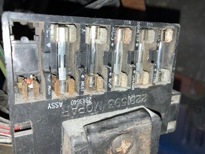
Thanks again for the help!!! After I'd gotten the car cruising around the high desert of LA, I started going through the shakedown of what needed to be addressed. That turned into exhaust, all brakes/drums (date code on brake hose was 1993), front suspension, torsion bars, shocks, steering gear, but I wanted to share a pic of what got me started on the harness! I figured since I was replacing everything and going back to brand new wiring, I could just connect the ammeter (or get a refurbed one) and leave it at that since I'd just put in an aftermarket stereo to start. These were my daily drivers from 1981 to 1989 (3 Darts, Cuda, GTX, and two Road Runners) and I never had fires, etc. I worked part time at a gas station and had lots of mechanic friends and cousins who raced at dirt tracks so I had lots of help if I needed it. But, EFI, electric fans, etc. were not an option back then so maybe I never stressed the system. All I remember is vapor lock and planning on an overheating during the summers. Anyway, I just want to make sure that I'm following the best way to future proof the car for modern tech (if I add any) and I REALLY appreciate all of the help...


Similar threads
- Replies
- 1
- Views
- 653
- Replies
- 14
- Views
- 1K
- Replies
- 10
- Views
- 1K


