• When you click on links to various merchants on this site and make a purchase, this can result in this site earning a commission. Affiliate programs and affiliations include, but are not limited to, the eBay Partner Network.

Bulkhead connectors orientation on schematic

If you would have explained yourself better, it would have improved matters immensely.
From here, it looked like a guy looking at a map who was unable to make any sense from it. Others saw and understood, but it seemed like you were lost.
You claiming to be an electrical engineer made no difference from where we stood as outsiders. To me, it looked like there was a stumbling block you couldn't see past.
No offense meant. When I see members here ask for help with something in a field where I feel that I can assist, I jump right in.
Cheers.
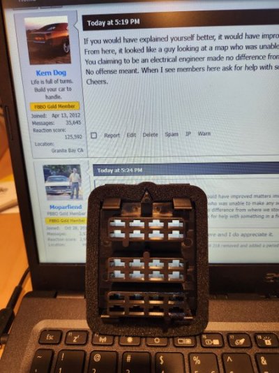
You have been helpful KD like many others here and I do appreciate it.
 
I never noticed that.
Are these the letters you never noticed?

IMG_7564.jpeg
 
58 year old eyes.....

Dash 2 V.jpg


I've never noticed the markings of numbers or letters.
 
Guys your making way too big of a deal with this. All I was doing was asking for confirmation on how to view the connector. I got that like in the third post that was enough but then you guys keep going on, and on saying how many post this is going to be, and then contributing to it especially Kiwi.
As I explain, my harness was fucked up, it had wires that didn’t belong there. The ones that were not very traceable because they were so badly aged. Some wires were placed in there that didn’t belong. This is why I was having difficulty. Is that so hard to understand. I feel myself biting my tongue asking for help here. I thought that this was why the site was even made. I’ve had good experiences here and really didn’t expect to have to keep explaining something so simple. If you think this post shouldn’t have been posted then just ignore it and move on. I got better things to do with my time as well. I don’t put anyone down here wrt their ability to understand electronics or anything else. I am electrical engineer with a masters degree. I’ve designed electronics that are on Air Force One. I design RF communication equipment, satellite equipment RF power amplifiers. I designed Motorola cell phones anf RFIC’s and I worked for them for over 15 years as well as semiconductor companies. I’m not trying to rub this in anyone’s face but to write me off like you guys are doing is really ignorant and I’m really disappointed.
Somebody needs a group hug.
 
And I helped…just like Stovetop. Use half a can. Spontaneous Combustion in-waiting.

80384F4A-6948-4D8F-BEAC-93DF10F0E3F2.jpeg
 
Trying to trace out some wires and due to age discoloration and I am finding this more challenging than it should be.

What orientation are the connectors in the schematic? Is the top really the top and are the wires viewed from the inside of the connectors or dead on as you see them plugged in

Thanks
MF
View attachment 1654619
The connectors are shown UNplugged and connectors facing viewer (so to speak), one has to look at the picture in a way that says "Ok so when I plug this together, J is Top Left and N is bottom right" Once you have the COLORS associated in mind it'll make sense. Personally I have to think upside down or from another angle. ALSO with many cars, these FSM diagrams aren't 100% EXACT for every car, per-say. This is usually only noticed with the low production number types:
-[a Dodge A12 Super Bee being the bare bones no frills car it is, will have a DASH harness that's really closer to a 69 Dart with a 383 or a GTS.]- Being that there are no extra courtesy lights, buzzers or even radio & speakers! When I worked in M&H we always built the harness to Include every option. Except for A/C or tailgate glass..
 
Some people must enjoy the attention of not being able to understand something as simple as a clearly defined answer.

I could dumb it down a bit, but to be honest my time is worth more than that to me right now.
Yup, take a look at the plug and READ THE LETTERS and the schematic will, suddenly, make sense, especially when the wires are so old that you can't distinguish the colors anymore.

Ford and GM schematics are the same as well. Hell, even Freightliner, Navistar, Hino, Toyota and on and on use the same system. They ALL have letters or numbers to identify plug cavities.

This arrangement prevents mistakes. It's an industry standard.

If you're building a harness on the bench, you HAVE to know what cavity the wire goes into.

THAT'S WHY THE CAVITIES ARE IDENTIFIED BY NUMBERS OR LETTERS.

The SAFEST way to fix a wiring issue at the firewall connection is to UNDERSTAND the design of the plug and the relationship of the plug to the schematic.

Here's a question for all of you naysayers, what happens if someone previously repaired/replaced the circuit(s) with the wrong colored wires? Where would all of you experts be, now?

FWIW, a '69 Camaro firewall plug is read UPSIDE DOWN. ROW "A" IS ON THE BOTTOM.

You have to unplug the connector and take a look at the letters/numbers molded into the connector. It's a simple as that.
Thanks.
I went out and took pictures of my spare empty bulkhead connectors to prove a point last week....but ran out of ******.

20240429_214135.jpg

20240429_214200.jpg
 
Auto Transport Service
Back
Top