• When you click on links to various merchants on this site and make a purchase, this can result in this site earning a commission. Affiliate programs and affiliations include, but are not limited to, the eBay Partner Network.

Dialing in a bellhousing

joe smith

Well-Known Member
Local time
1:43 PM
Joined
Jan 4, 2018
Messages
1,574
Reaction score
2,008
Location
Florida
Been watching videos, reading up on this etc... LOL.. NEVER did this in the " old days" with 4 speeds, but I understand my new TKX needs to have tighter variances

My question is I still don't understand how you can get the correct numbers without the Dial indicator being in the exact center of the crank shaft, which is NOT being done on the video's I have been watching...
What am I missing? Just a simple man here, not too technical please....
The dial indicator still turns in the same.....plane. A circle is a circle. Think of a fan blade. Each blade is going to turn in the same radius. Another way is to not worry about it. Just make sure the dial indicator is on a large enough stem to not have any sag whether or not you screw it into a bolt hole or bolt on a flywheel and use a strong mag base.
 
Cranky is correct, on my 440 4/s , took old flywheel bolt and welded a nut to it , screwed stem that would have gone into the magnet, to get it secure! With flywheel torqued correctly and then removed one bolt and attached my bolt nut combo!
 
Because you are measuring from one point (where ever the dial indicator stand is located) and it is riding in a perfect circle around the inside of the hole in the bell. That circular path is the same of the crank which you are rotating to spin the indicator. I would make a stand for the mag base of the indicator out of a section of 3/16" flat stock ground flat on one side (mag side) and drilled for two opposing holes in the crank flange. There isn't enough meat at the center of the flywheel or crank flange stand to mount the mag base of most dial indicators. You need to have repeatable measurements and it starts with the indicator being locked down.

In practice, if your max positive measurement is at 9 oclock and measures a +.007 on the indicator you will be looking to see -.007" at 3 oclock. This tells you that the bell will be centered with theoretically "zero runout" if you locate it .0035" towards 3 oclock. That would be checked by making the adjustment, re-zeroing the indicator and you should see close to 0. The bellhousing register hole is usually not perfectly round especially if it uses an adapter- ring (Lakewood, Quicktime, etc) are known to be as much a .0015" out of round.

Therein lies the tricky part; you must get enough dial indicator readings to help figure out which way to move it. This is best accomplished by making adjustments between the two largest + and - measurement points. Adjust, re-zero and repeat until you are in spec.

The entire process is much easier with a helper to turn the engine over.

If you are performing this with an explosion proof bellhousing you will want to make sure you torque it to spec each time measurements are taken.

Let us know how it turns out.
 
Just go by the video, and pretend it's your bell housing. Make sure your indicator is mounted very solid and that it repeats
to zero every time you get back to your low point! Me being a machinist, before I start I would really like to know if the two bolting faces were parallel. Guessing is not an option. Have a machine shop check the bell housing on a surface plate first.
 
Been watching videos, reading up on this etc... LOL.. NEVER did this in the " old days" with 4 speeds, but I understand my new TKX needs to have tighter variances

My question is I still don't understand how you can get the correct numbers without the Dial indicator being in the exact center of the crank shaft, which is NOT being done on the video's I have been watching...
What am I missing? Just a simple man here, not too technical please....
360 degrees is still 360 degrees….being a retired Tool and Die Maker…..indicating does not need to be true center of part…..what your seeing in your video is accurate……
 
Been watching videos, reading up on this etc... LOL.. NEVER did this in the " old days" with 4 speeds, but I understand my new TKX needs to have tighter variances

My question is I still don't understand how you can get the correct numbers without the Dial indicator being in the exact center of the crank shaft, which is NOT being done on the video's I have been watching...
What am I missing? Just a simple man here, not too technical please....

Hoping this means you've decided to keep your Coronet R/T & make it a 5 Spd????
 
I was doing this and my neighbor (Engineer) came over to tell me it wouldn’t work because it wasn’t centered. “You can’t just put that on there and start spinning it”. He proclaims. So I did it and I marked the hi and low numbers on the bellhousing, then moved the dial indicator base on the crank and did it again, it was the same of course. He shut up and went home. LOL
 
Take a compass and draw a 2" diameter circle on a piece of paper. Using the same center point draw a larger circle. Now, using a ruler, measure the distance between the two circles at various points. The measurements are the same, right? So consider the inner circle to be the dial indicator mounting point and the circle is it being rotated as you turn the crank. The outer circle is the bellhousing hole. Only with the dial indicator you're measuring how far off the outer circle is from the inner - in thousandths of an inch !
 
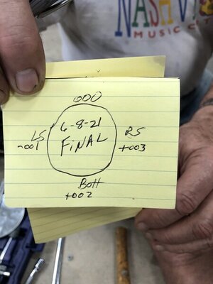
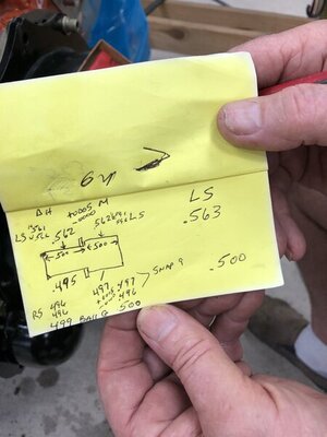
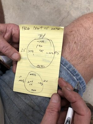
These were the b4 and after results when I centered mine:

As you can see the QT housing was .015” off to start

The trick is to get Dowell pins corrected so the housing goes back to center every time.

Once the housing is locked down tight on center, we precisely drilled and reamed both sides of the dowel holes to the same size and turned new Dowell pins on a lathe to +.002” on the block side and -.001-2” on the housing side.

The final pic. is of the new dowel dimensions. Smaller on the housing side so it comes off and larger on the block so it remains fixed.

My brother in law is a steam turbine mechanic and he taught me that trick.

B4277D78-EB11-48E4-B20B-43FBCFB23BC0.jpeg 9312598B-7877-4B82-853C-6CAE0D939115.jpeg
 
Hoping this means you've decided to keep your Coronet R/T & make it a 5 Spd????
LOL, you have been doing your homework Randy.....
No, the dodge is getting some paint chips fixed right now before going on Bring a Trailer..
My son passed away last year ( Drugs ) and I inherited his 83 mustang, that my sister bought in 84/85....
A simple car I am making a "Grocery getter" out of.. I have been Having alot of fun with this car...
Pulled the 302/SROD 4speed, and the 7.5" rear end... Rebuilt an Explorer 302 with GT40P heads , installing a TKX, and a "bolt in" 9"....

All done with Garage queens, and I hope my Dodge I have owned for 31 years finds a good home with someone who can appreciate the love it has gotten,,
 
Last edited:
DSCF0834.JPG
Before I get off topic here, thanks for all the help on here....
I think the best video I watched was from Bowlers Transmissions... Good explanations on some of the simpler items that others pass by...

Here it is..... DSCF0840.JPG
 
Last edited:
These were the b4 and after results when I centered mine:

As you can see the QT housing was .015” off to start

The trick is to get Dowell pins corrected so the housing goes back to center every time.

Once the housing is locked down tight on center, we precisely drilled and reamed both sides of the dowel holes to the same size and turned new Dowell pins on a lathe to +.002” on the block side and -.001-2” on the housing side.

The final pic. is of the new dowel dimensions. Smaller on the housing side so it comes off and larger on the block so it remains fixed.

My brother in law is a steam turbine mechanic and he taught me that trick.

View attachment 1195602 View attachment 1195603
That’s almost dead nuts….a term used by Tool and Die Makers…..working within +/-.0002 most of my life those are excellent figures on your bell housing..
 
Auto Transport Service
Back
Top