• When you click on links to various merchants on this site and make a purchase, this can result in this site earning a commission. Affiliate programs and affiliations include, but are not limited to, the eBay Partner Network.

Help with a sending unit please

moparedtn

I got your Staff Member riiiight heeeere...
FBBO Gold Member
Local time
8:24 AM
Joined
May 14, 2011
Messages
17,245
Reaction score
32,447
Location
On the Ridge, TN
Recently, I obtained a "proper" fuel sending unit via Sale ad here on FBBO (thanks, @Road Grabber ).
Least, I think it is - I don't see any part numbers on it, but it appears to be an original...
3/8" out, 1/4" return line, all that jazz. Even has a sock still.

Anyways, today I decided to check it out in preparation for eventual installation in place of the piece
of CRAP Chinesium one in Fred now.
I remembered a recent discussion about the resistance test of one of these and decided to give it a go.
At first, nothing much was working, so I got inside the swinging part of the sender and cleaned up the
contact "sweep" and the little brass bobber thingy on the pendulum, then buttoned it back up.

I set my test meter to ohms and here's what I got:
IMG_20231008_150340761.jpg

Float arm resting against one of the stops...black ground probe tucked up under the corner of the outside
of the little box, wedged between it and the 3/8" tubing. Red probe is connected to the threaded stud where
the wire going to the gauge attaches....

IMG_20231008_150350868.jpg

Float arm sort of at 1/3 travel....

IMG_20231008_150359760.jpg

...and finally, float arm held up against the other stop.

I only was able to get these variable readings after doing some cleaning up of the contact surfaces of the inner
workings AND re-bending the little brass arm on the shaft coming in from the float so that it made really positive
contact with that isolated strip inside the box, the one with all the "teeth" on it.

(Funny side note: this strip showed what looked like "never got fill-ups" wear on it; the far end of one side of it
was noticeably less swept-upon than the bulk of the rest of the strip).

I'm thinking I've got the delicate little thing working again, so now I need to go about making it a bit more bulletproof
before I go to all the hassle of getting under the car and swapping it for the junk sender in there now.
Suggestions?
Example: One of the three tabs that holds the little box together is broken off, so I'll want to give a few spot solderings
along that edge of the seam I think.

BTW, question: Now, don't make fun of me, but I'm not sure what the meter readings mean - seems like a swing of 50
ohms or so? My meter (I think a decent one) only has one ohms ("continuity") position on the switch. Are these numbers
good or do they indicate an overall issue?

Thanks in advance!
 
The resistance should range from 20ish ohms full to 90ish ohms empty, 50ish for half a tank. This is a NOS 68-70 sender.

IMG_3326.JPG
IMG_3327.JPG
 
I went back out to the garage and investigated the meter further - and there's no alternative scales/ranges
when it's in ohms mode, so that's out.
I then systematically started working my way back from the gauge connector (a much stouter piece than the
one pictured above, no offense) and checking the wire, the connection points, all that to see if any were contributing
to the interesting readings I was getting.
Connector was good, connector through wire to box good... but when I moved the probe from the wire end to the
actual pin that passes through the box housing, things went up to the same range as before.
I reckon the little brass rivet that passes through the box housing wall and connects the outside wire to the inside
workings is in need of drilling out and replacing?
 
Yup, sounds like there is high resistance at that connection. You want the readings to be good where the gauge wire and ground connects.
 
…BTW, question: Now, don't make fun of me, but I'm not sure what the meter readings mean - seems like a swing of 50
ohms or so? My meter (I think a decent one) only has one ohms ("continuity") position on the switch…

I went back out to the garage and investigated the meter further - and there's no alternative scales/ranges
when it's in ohms mode…

Ed, it sounded like you had a meter question too? Forgive me if I misunderstood you here.
In multimeters such as yours and the Fluke @T2R9 is showing…if the selector only has (1) position for resistance it is typically “auto-ranging”. Saves the user from having to know the range of value of what they’re measuring.
With the less expensive multimeters, the user has to manually select their range from several switch position options. This can be a bit confusing sometimes for first time users.
 
I thought Ma Mopar senders were between 10-73 ohms

Have you zero'd the meter or touched leads to see what the starting reading is @moparedtn ?

If the meter gives wild fluctuations on the ohms reading while gently moving through the sweep, I would say the sender has issues. It should transition smoothly and evenly - except some will read faster on the top & bottom of the sweep movement (if you know what I mean)
 
Here's any easy test Ed.

Grab a cable from a set of jumper leads, and attach the frame of the sender unit - the other end to a good ground on the car - tail light housing or something.

Run another small cable from the blue sender wire on the existing tank in the car - to the replacement sender unit.

Test from full sweep to zero on the float arm....see what happens. You might need an assistant to move the arm while you watch the gauge.
Be aware that the gauge moves slowly.
 
I thought Ma Mopar senders were between 10-73 ohms

Have you zero'd the meter or touched leads to see what the starting reading is @moparedtn ?

If the meter gives wild fluctuations on the ohms reading while gently moving through the sweep, I would say the sender has issues. It should transition smoothly and evenly - except some will read faster on the top & bottom of the sweep movement (if you know what I mean)
Yes, I tested the meter on all manner of metal objects, then on the sending unit itself as I've detailed.
It "starts" at 0L like most I've seen do - and shows full continuity both audibly and on screen.

The sweep of the float arm generates a very even, gradual increase/decrease (now that I've gutted and cleaned
the thing a few times) - but it appears the actual brass rivet that passes through the housing to the wire
has a ton of resistance in it, no doubt from corrosion.
Everything else checks out, far as I can tell.

Oh, PS - the isolated rub strip inside the box that the pintle on the float rod scrapes on appears to be quite worn.
It's working right now, but longevity is obviously a concern, especially when the worn parts are compared to the
bit of it at one end that obviously didn't see any action in its' lifetime of service.

It now appears I've bought an (admittedly rare) sending unit - that needs rebuilding.
 
Really?
My info was something close to mid 70s empty and mid teens full.
Another thing...ALL aftermarket senders are inaccurate between 3/4 and 1/4. The factory built originals with an elliptical fuel curve, the aftermarket ones are linear. They are close to accurate from full to 3/4 and from 1/4 to empty. Everything in between is different between the OEM and aftermarket.
Aftermarket? We're not discussing aftermarket stuff here.
I have one of those installed in Fred now - and it's typically junk inaccurate., hence why I went
for this original one when it was offered to me for sale.
Problem is, it's not a new unit - and in reality now that I've taken time to check it out, it's going
to need some restoring in order to be useable at all (if parts are even available, that is).
 
Thanks Wayne. I saved those to my files.
I thought the ohms numbers I had heard were in line with yours, give or take a few. 90+ seemed wrong.
One thing just occurred to me....The elliptical curve in the factory senders may be that way due to the irregular shape of the fuel tank. It isn't a square box where it is easy to calibrate (One inch= One gallon. The sloped bottom of the tank makes it NON linear.
 
Yes, I remember the 10-70 bit from your post earlier this year Wayne, thanks.
That doesn't actually answer any of my questions here though...

If anything, I'm encouraged in getting the internals actually working and giving me an over 50ohm range
smoothly - and I think I've narrowed down where the gigantic by comparison additional resistance is coming
from, too.

Unfortunately, the "sweep plate" in this thing is quite worn in the expected places, so even if I drill out rivets
and clean up the high resistance sources, I'm still going to be left with a sending unit that doesn't have much
of a life expectancy.

Here's any easy test Ed.

Grab a cable from a set of jumper leads, and attach the frame of the sender unit - the other end to a good ground on the car - tail light housing or something.

Run another small cable from the blue sender wire on the existing tank in the car - to the replacement sender unit.

Test from full sweep to zero on the float arm....see what happens. You might need an assistant to move the arm while you watch the gauge.
Be aware that the gauge moves slowly.
Thanks, but not that easy for me, crawling under the car to fetch that wire loose....
and honestly, that'd be a great test for someone without use of a meter.
As it is, with this huge resistance issue, this sending unit would only peg the gauge and stay there,
regardless of where I sweep the arm.

On a slightly encouraging note, at least the brass float has tested leak-free. Yippee.
 
Thanks, but not that easy for me, crawling under the car to fetch that wire loose....
:thumbsup:

Best I don't suggest removing the driver's seat and crawling under the dash to directly connect to the back of the gauge......or, better still.........

Undo the left hand (driver's side) kick panel and locate the blue wire at the front of the sill plate cable protecting cover......I cannot remember if it is in a multi-way terminal block - or going directly to the gauge.

If the wire is not passing through a connector which can be pulled apart - you could 'stab' the wire carefully to make contact with the copper and use the same method I described above to test the sender unit closer to the gauge.
Again - all of that is spiffy and all, but if I already know the sending unit on my bench has serious flaws,
I don't need verification of that by inflicting it upon Fred, too.
 
I guess if I feel like trying to fix this one, I'll have to drill out the rivet and clean up the end of the wire
outside the box, as well as the end of the contact strip "ribbon" inside, then piece it all back together
with a small brass screw and nut (and utilizing the original isolators now on either side of the rivet).
What would be a good substitute isolator washer to use if I need to?
One that will obviously need to be gas-resistant.
 
Really?
My info was something close to mid 70s empty and mid teens full.

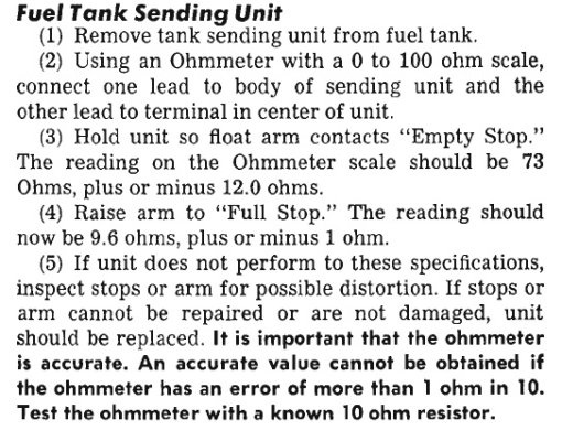
I stand corrected. My manual says 73 +-12 empty and 9.6 +-1 full. Proves I should RTFM first, LOL.
 
1968 Factory Service Manual:
sending1.jpg

sending2.jpg

sending3.jpg
Now, if only I had a decent sending unit....
Oh well, you pays yer money and you takes yer chances.
 
Auto Transport Service
Back
Top