If what you have is indeed an oem 3/8" sender, I would be tickled pink to own it, and would gladly send it off for a rebuild. Those are extremely hard to find nowadays.
You are using an out of date browser. It may not display this or other websites correctly.
You should upgrade or use an alternative browser.
You should upgrade or use an alternative browser.
Help with a sending unit please
- Thread starter moparedtn
- Start date
- Local time
- 10:26 PM
- Joined
- May 14, 2011
- Messages
- 18,959
- Reaction score
- 38,321
- Location
- On the Ridge, TN
Well, it supposedly is - you see the pics - but hey @dadsbee , is there a part number stamped on these anywhere if they'reIf what you have is indeed an oem 3/8" sender, I would be tickled pink to own it, and would gladly send it off for a rebuild. Those are extremely hard to find nowadays.
original Mopar?
- Local time
- 10:26 PM
- Joined
- Jan 29, 2018
- Messages
- 21,982
- Reaction score
- 70,579
- Location
- Midland Ontario, Canada
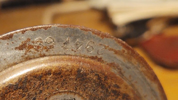
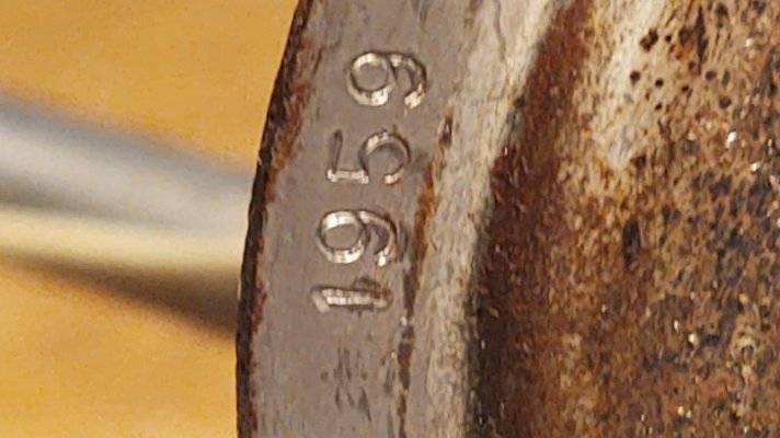
Yep, part #, mfg's # and mfg date on the face of the outer edge.


- Local time
- 10:26 PM
- Joined
- May 14, 2011
- Messages
- 18,959
- Reaction score
- 38,321
- Location
- On the Ridge, TN

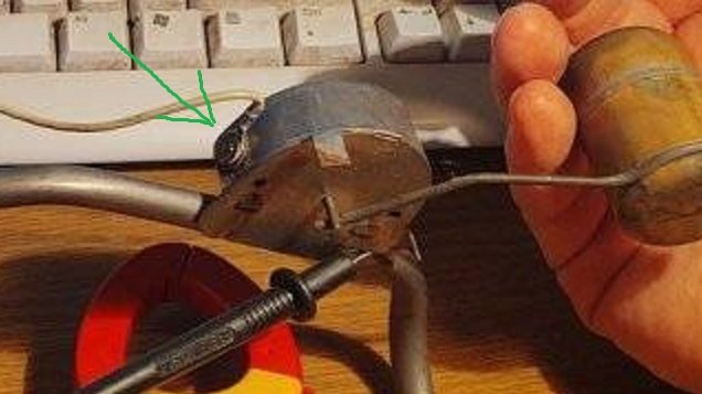
The big measured resistance occurs here, between the eyelet on the end of the wire and the brass rivet
that passes through the outer shell of the "box". There's a black-colored insulator washer of some sort
there as well that seems to still be doing the job.
On the inside, the rivet connects the rub strip that the little brass pendulum sweeps as the float moves.
On the other end of that strip, it's attached to the box itself by another rivet to complete the circuit.
I could drill out this brass rivet (carefully!) and clean up all the contact points, then put the connection
back together with some sort of brass screw and nut I guess?
- Local time
- 10:26 PM
- Joined
- May 14, 2011
- Messages
- 18,959
- Reaction score
- 38,321
- Location
- On the Ridge, TN
Well, looky here....Yep, part #, mfg's # and mfg date on the face of the outer edge.
View attachment 1537550View attachment 1537551View attachment 1537552View attachment 1537553


Looks like it's a real one @hunt2elk . Thanks Wayne @dadsbee - and thanks NevRDull.

Road Grabber
Well-Known Member
- Local time
- 10:26 PM
- Joined
- Apr 14, 2020
- Messages
- 1,095
- Reaction score
- 338
- Location
- Sarasota Florida/NY State
Recently, I obtained a "proper" fuel sending unit via Sale ad here on FBBO (thanks, @Road Grabber ).
Least, I think it is - I don't see any part numbers on it, but it appears to be an original...
3/8" out, 1/4" return line, all that jazz. Even has a sock still.
Anyways, today I decided to check it out in preparation for eventual installation in place of the piece
of CRAP Chinesium one in Fred now.
I remembered a recent discussion about the resistance test of one of these and decided to give it a go.
At first, nothing much was working, so I got inside the swinging part of the sender and cleaned up the
contact "sweep" and the little brass bobber thingy on the pendulum, then buttoned it back up.
I set my test meter to ohms and here's what I got:
View attachment 1536826
Float arm resting against one of the stops...black ground probe tucked up under the corner of the outside
of the little box, wedged between it and the 3/8" tubing. Red probe is connected to the threaded stud where
the wire going to the gauge attaches....
View attachment 1536827
Float arm sort of at 1/3 travel....
View attachment 1536828
...and finally, float arm held up against the other stop.
I only was able to get these variable readings after doing some cleaning up of the contact surfaces of the inner
workings AND re-bending the little brass arm on the shaft coming in from the float so that it made really positive
contact with that isolated strip inside the box, the one with all the "teeth" on it.
(Funny side note: this strip showed what looked like "never got fill-ups" wear on it; the far end of one side of it
was noticeably less swept-upon than the bulk of the rest of the strip).
I'm thinking I've got the delicate little thing working again, so now I need to go about making it a bit more bulletproof
before I go to all the hassle of getting under the car and swapping it for the junk sender in there now.
Suggestions?
Example: One of the three tabs that holds the little box together is broken off, so I'll want to give a few spot solderings
along that edge of the seam I think.
BTW, question: Now, don't make fun of me, but I'm not sure what the meter readings mean - seems like a swing of 50
ohms or so? My meter (I think a decent one) only has one ohms ("continuity") position on the switch. Are these numbers
good or do they indicate an overall issue?
Thanks in advance!
I’ve had to solder after breaking tabs off too. If you can get a good ground at your hook up under the car and connect the sender I would think you could see what your gauge is reading at different positions. That’s if the gauge is in good shape. The gauge should pin full when you give full battery power.
Hope this helps. Sorry took so long it’s been crazy here with winter on the way. Been taking wife for health treatment.
- Local time
- 7:26 PM
- Joined
- Apr 13, 2012
- Messages
- 41,565
- Reaction score
- 151,256
- Location
- Granite Bay CA
For as long as we have all complained about the crappy readings of aftermarket senders, it is a shame that some enterprising enthusiast has not stepped up to make a decent reproduction sending unit.
There was a guy on another forum that took deposits to gather seed money to do this very thing many years ago. His deal with a builder fell through and he had to refund all the money. It was disappointing because many of us get accustomed to how our later model daily drivers are and when our "restored" classics have issues like this despite being mechanically sound in other areas, it really sucks.
I know this is off topic but when we start chatting about sending units, this often comes up.
- Local time
- 10:26 PM
- Joined
- Jan 29, 2018
- Messages
- 21,982
- Reaction score
- 70,579
- Location
- Midland Ontario, Canada
Why I made my chart, so I could convert the crapola's. But life gets in the way.. constantly! LOLFor as long as we have all complained about the crappy readings of aftermarket senders, it is a shame that some enterprising enthusiast has not stepped up to make a decent reproduction sending unit.
There was a guy on another forum that took deposits to gather seed money to do this very thing many years ago. His deal with a builder fell through and he had to refund all the money. It was disappointing because many of us get accustomed to how our later model daily drivers are and when our "restored" classics have issues like this despite being mechanically sound in other areas, it really sucks.
I know this is off topic but when we start chatting about sending units, this often comes up.
By some of the discussions here, it sounds like there is a source for rebuilding the sender. Who does this? Also, who is making a sender gasket thats not a pos?
Similar threads
- Replies
- 14
- Views
- 347
- Replies
- 27
- Views
- 1K
- Replies
- 47
- Views
- 4K


