The purpose of this thread is help share what I did to upgrade my alternator and wiring in my 1970 Road Runner. Before I start, three caveats:
1) I am NOT professing to be Joe expert, so I welcome alternate suggestions, thoughts, etc.
2) While I believe most old Mopars to be the same, these are written based on my 1970 Road Runner.
3) There are other totally acceptable ways to upgrade wiring, so this is NOT THE ONLY WAY - just the way I decided to do it.
Let's dig in:
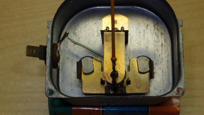
Before we talk about upgrading anything, let's cover the BASICS of the stock charging system and an alternator. Reference the attached picture below.

Issues with the stock system:
What I did to upgrade my system:
So ultimately what I have done with this setup is create two power circuits (and two fusible links). The original car wiring through connector P and an ability to power additional accessories through connector J. Since I did NOT replace the spade connectors at the firewall, they are still weak points. However, I have split the load of my system through two connectors rather than putting it all through one. This would not be a good way to go if you are planning on a lot of additional power accessories. Then you would be best to drill through the firewall and route a separate power wire directly into the car. In my case, I wanted to keep the car as stock (and reversible) as possible.
Sorry for the long post, but I hope folks find this helpful. It is late and I have had a beer, so please set me straight if I said something stupid above. :icon_confused: Also, I would be happy to help clarify my description(s) if I did a lousy job.
Hawk
1) I am NOT professing to be Joe expert, so I welcome alternate suggestions, thoughts, etc.
2) While I believe most old Mopars to be the same, these are written based on my 1970 Road Runner.
3) There are other totally acceptable ways to upgrade wiring, so this is NOT THE ONLY WAY - just the way I decided to do it.
Let's dig in:
Before we talk about upgrading anything, let's cover the BASICS of the stock charging system and an alternator. Reference the attached picture below.
An alternator gauge measures current direction and flow. When the needle is centered, there is no current flow in or out of the battery. When discharging, current is flowing out of the battery. The greater the deflection of the needle, the more power is being sucked out of the battery. In the opposite direction, the more the needle deflects, the more power is being charged back to the battery.
In the diagram, we will start at the battery near point A (lower left in the picture). Current flows from the battery through a wire that connects at the starter relay. The wire that comes out of the starter relay is a fusible link (I will say it is required, but we can argue about fuses vs. fusable links on another thread ). The fusible link connects at the firewall at point B. The connector is marked J. Inside the car, this is a red wire that goes to the alternator gauge (see circle at right hand side of the picture).
On the other side of the gauge, the wire is black. It disappears into the wiring, but this black wire ultimately connects to a number of power sources, including the battery +12V fuse panel Point D (not switched sources though). Point C shows the connection point.
Past the connection point, the black wire connects at the firewall at point B. This is connector P. Under the hood, connector P is the black wire that goes straight to the alternator.
Clear as mud? Note this is NOT a circuit (a full circuit goes from power to ground - This is the +12 volt side of the car power only). When using power from the battery, power flows from the battery, through point B, through the alternator gauge, to connection point C, and off to the stuff that is using power. When the alternator is powering stuff, current flows through the point B to connection point C and off to the stuff that is using power. As needed, the alternator also sends power through the alternator gauge, back through the red wire and point B, and back to the battery.
Issues with the stock system:
The stock system has two major weak points. The first is that it uses 12 gauge wire. This wire is a bit too thin to handle anything over 50 amps. The second, and probably greatest issue, is that ALL the car's power goes through either connector J or P. This is a small spade connector and it really CANNOT handle 50 amps. This is the major weak point in the system.
One other concern is that all the car's power routes through one alternator gauge with connectors in the dashboard. All that power through one gauge is also not the safest thing to do.
What I did to upgrade my system:
The first thing I did was had my alternator gauge converted to a voltmeter. A voltmeter does not measure how much current is flowing, just the level. Think of it like a garden hose. Current would be how much water is flowing through the hose. Voltage is the pressure of the water. You can still measure the water pressure without any flow of water. I hope that makes some sense...
OK, so now the voltmeter measures voltage, which it does right from the printed circuit panel on the back if the instrument cluster. You COULD simply connect the black and red wires together and do nothing else, but then all you have done is removed the alternator. The same issues still exist.
To upgrade the wiring capability, I removed the under hood alternator to connector P wire. I replaced the wire with 10 gauge stranded wire. This wire is good for up to about 65 amps (I don't need more than that). If you want more power than that, then you should go with an 8 gauge wire that can handle up to about 85 amps. Use 6 gauge for up to 100 amps.
Note that this new wire no longer goes to connector P. Instead, it goes from the alternator to the starter relay - the same stud where the fusible link is connected.
Now there is no power going into the car, so I added an additional fusible link from the starter relay to connector P.
In my case, I have NOT connected the alternator gauge black and red wires together. The black wire is just wrapped up with tape and not used (it will be hot with +12v, so protect it well).
The new fusible link, from the starter relay through connector P, now powers the stock system.
The original fusible link, through connector J, goes to a red wire behind the alternator and does NOTHING. In my case, I will use that red wire to power a separate fuse panel. This fuse panel can have both switched and non-switched power if I add a relay and some additional wiring (subject of a separate post later). I plan to power my additional accessories with this new fuse panel.
The wire running from the battery to the starter relay also needs to be upgraded as well to the same size wire that runs from the alternator. In my case, that is a 10 gauge wire.
So ultimately what I have done with this setup is create two power circuits (and two fusible links). The original car wiring through connector P and an ability to power additional accessories through connector J. Since I did NOT replace the spade connectors at the firewall, they are still weak points. However, I have split the load of my system through two connectors rather than putting it all through one. This would not be a good way to go if you are planning on a lot of additional power accessories. Then you would be best to drill through the firewall and route a separate power wire directly into the car. In my case, I wanted to keep the car as stock (and reversible) as possible.
Sorry for the long post, but I hope folks find this helpful. It is late and I have had a beer, so please set me straight if I said something stupid above. :icon_confused: Also, I would be happy to help clarify my description(s) if I did a lousy job.
Hawk
Last edited:
 ccasion14: