• When you click on links to various merchants on this site and make a purchase, this can result in this site earning a commission. Affiliate programs and affiliations include, but are not limited to, the eBay Partner Network.

How To: Upgrading Wiring and Alternator

HawkRod

Formerly hsorman
Staff member
FBBO Gold Member
Local time
4:02 PM
Joined
Aug 8, 2011
Messages
6,613
Reaction score
13,953
Location
Lansdale, PA
The purpose of this thread is help share what I did to upgrade my alternator and wiring in my 1970 Road Runner. Before I start, three caveats:
1) I am NOT professing to be Joe expert, so I welcome alternate suggestions, thoughts, etc.
2) While I believe most old Mopars to be the same, these are written based on my 1970 Road Runner.
3) There are other totally acceptable ways to upgrade wiring, so this is NOT THE ONLY WAY - just the way I decided to do it.

Let's dig in:
Before we talk about upgrading anything, let's cover the BASICS of the stock charging system and an alternator. Reference the attached picture below.
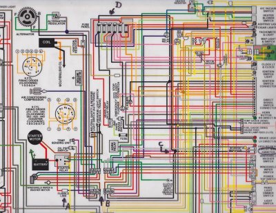
  • An alternator gauge measures current direction and flow. When the needle is centered, there is no current flow in or out of the battery. When discharging, current is flowing out of the battery. The greater the deflection of the needle, the more power is being sucked out of the battery. In the opposite direction, the more the needle deflects, the more power is being charged back to the battery.

  • In the diagram, we will start at the battery near point A (lower left in the picture). Current flows from the battery through a wire that connects at the starter relay. The wire that comes out of the starter relay is a fusible link (I will say it is required, but we can argue about fuses vs. fusable links on another thread :icon_fU:). The fusible link connects at the firewall at point B. The connector is marked J. Inside the car, this is a red wire that goes to the alternator gauge (see circle at right hand side of the picture).

  • On the other side of the gauge, the wire is black. It disappears into the wiring, but this black wire ultimately connects to a number of power sources, including the battery +12V fuse panel Point D (not switched sources though). Point C shows the connection point.

  • Past the connection point, the black wire connects at the firewall at point B. This is connector P. Under the hood, connector P is the black wire that goes straight to the alternator.

  • Clear as mud? Note this is NOT a circuit (a full circuit goes from power to ground - This is the +12 volt side of the car power only). When using power from the battery, power flows from the battery, through point B, through the alternator gauge, to connection point C, and off to the stuff that is using power. When the alternator is powering stuff, current flows through the point B to connection point C and off to the stuff that is using power. As needed, the alternator also sends power through the alternator gauge, back through the red wire and point B, and back to the battery.
SCN_0002.jpg

Issues with the stock system:

  • The stock system has two major weak points. The first is that it uses 12 gauge wire. This wire is a bit too thin to handle anything over 50 amps. The second, and probably greatest issue, is that ALL the car's power goes through either connector J or P. This is a small spade connector and it really CANNOT handle 50 amps. This is the major weak point in the system.

  • One other concern is that all the car's power routes through one alternator gauge with connectors in the dashboard. All that power through one gauge is also not the safest thing to do.

What I did to upgrade my system:

  • The first thing I did was had my alternator gauge converted to a voltmeter. A voltmeter does not measure how much current is flowing, just the level. Think of it like a garden hose. Current would be how much water is flowing through the hose. Voltage is the pressure of the water. You can still measure the water pressure without any flow of water. I hope that makes some sense...

  • OK, so now the voltmeter measures voltage, which it does right from the printed circuit panel on the back if the instrument cluster. You COULD simply connect the black and red wires together and do nothing else, but then all you have done is removed the alternator. The same issues still exist.

  • To upgrade the wiring capability, I removed the under hood alternator to connector P wire. I replaced the wire with 10 gauge stranded wire. This wire is good for up to about 65 amps (I don't need more than that). If you want more power than that, then you should go with an 8 gauge wire that can handle up to about 85 amps. Use 6 gauge for up to 100 amps.
    Note that this new wire no longer goes to connector P. Instead, it goes from the alternator to the starter relay - the same stud where the fusible link is connected.
    Now there is no power going into the car, so I added an additional fusible link from the starter relay to connector P.

  • In my case, I have NOT connected the alternator gauge black and red wires together. The black wire is just wrapped up with tape and not used (it will be hot with +12v, so protect it well).

  • The new fusible link, from the starter relay through connector P, now powers the stock system.

  • The original fusible link, through connector J, goes to a red wire behind the alternator and does NOTHING. In my case, I will use that red wire to power a separate fuse panel. This fuse panel can have both switched and non-switched power if I add a relay and some additional wiring (subject of a separate post later). I plan to power my additional accessories with this new fuse panel.

  • The wire running from the battery to the starter relay also needs to be upgraded as well to the same size wire that runs from the alternator. In my case, that is a 10 gauge wire.

So ultimately what I have done with this setup is create two power circuits (and two fusible links). The original car wiring through connector P and an ability to power additional accessories through connector J. Since I did NOT replace the spade connectors at the firewall, they are still weak points. However, I have split the load of my system through two connectors rather than putting it all through one. This would not be a good way to go if you are planning on a lot of additional power accessories. Then you would be best to drill through the firewall and route a separate power wire directly into the car. In my case, I wanted to keep the car as stock (and reversible) as possible.

Sorry for the long post, but I hope folks find this helpful. It is late and I have had a beer, so please set me straight if I said something stupid above. :icon_confused: Also, I would be happy to help clarify my description(s) if I did a lousy job.

Hawk
 
Last edited:
Thanks Hawk;

Not only is that a logical move for a mild upgrade - like you I don't need a lot more amp capability - but you went out of your way to explain some of the why behind the changes as well.
 
That's good info Hawk. I've been looking at a couple of different ways of going about this lately for my gtx. It's good to have an explanation on how and why things are wired up. Well done.
 
Good work Hawk on the electrical system!

I am upgrading the alternator in my Charger 67 stroker, and I will keep the original ammeter, which IMHO is a lot more useful than a voltmeter.
I have had a close look inside the original ammeter and seen nothing that can burn there, and certainly the screw terminals have to be tight and the proper wire size used.

I'm upgrading to a 100 Amp alternator, also upgrading the wires carrying the current, not using the J and P spade connectors (I go straight thru and add 2 higher power connectors under the dash), all the rest remains unmodified (except for some dedicated ground wires from the tail etc.). Certainly for the engine management I am having dedicated electrical stuff.

I don't expect any problems with this upgraded alternator design, and if I do...I will keep you posted! :icon_thumright:
 
Last edited:
Thanks for details! I'll be completely re-wiring the charger this winter. This info will help!
 
Good work Hawk on the electrical system!

I am upgrading the alternator in my Charger 67 stroker, and I will keep the original ammeter, which IMHO is a lot more useful than a voltmeter.
I have had a close look inside the original ammeter and seen nothing that can burn there, and certainly the screw terminals have to be tight and the proper wire size used.

I'm upgrading to a 100 Amp alternator, also upgrading the wires carrying the current, not using the J and P spade connectors (I go straight thru and add 2 higher power connectors under the dash), all the rest remains unmodified (except for some dedicated ground wires from the tail etc.). Certainly for the engine management I am having dedicated electrical stuff.

I don't expect any problems with this upgraded alternator design, and if I do...I will keep you posted! :icon_thumright:

From a gauge perspective, I completely agree with you: I prefer the ammeter over the voltmeter.

The screw terminals on the alternator gauge (ammeter) should not be the problem, but I would worry about the internals. I do not have the specifications for the original gauge to know what it can handle, but I would doubt it can handle anything close to 100 amps. Look at any multi-meter you buy. It will have a very specific current carrying capability, and can't just handle three times what it was designed for.

I would be worried if you truly put 100 amps through the gauge. I would be cautious if your gauge starts deflecting very far to either side - that could be a warning you are putting a lot of current through the gauge that it cannot handle.

Best of luck with your power upgrades!
 
I don't believe the amp gauge will see the full 100 amps. The amp gauge only sees the current flowing to the battery, controlled by the Voltage Regulator. While 12 gauge wire for a home use is limited to 20amps, that is because of the distance, Voltage drop, and other factors. Not that going to 10ga isn't safer.

The previous owner of my car (70 RR) had harness damage when the origional wire became frayed and grounded to motor. It was replaced with new. Later I inspected the dash and column wiring and found melted insulation and damage on the Blue ignition wire in the dash harness.

MOPAR sent the ignition wire into the center of the dash harness to a weld joint than back to the firewall terminal. All that extra wire length to feed an indicator light and a relay I believe. When I repaired it, the one change I made was to double wire the connector (dash harness side) coming out of the column (from the ignition switch) and sent it directly back out the firewall to feed the ignition. The second wire went to the center of the dash harness to feed the indicator light and relay. This reduced the length of the blue ignition wire carrying the main load to the engine compartment by about 5-6 feet, and in the event of another overload, does not expose the whole dash harness to damage. G
 
Running an alternator rated at 100 amps doesn’t mean anything close to 100 amps will be passing through the ammeter for any extended amount of time. The ammeter is in series to display battery charging current or drain only. All vehicle electrical load should be on the alternator side of the ammeter. Most ammeter problems can be traced back to either the over tightening or nuts too loose on the threaded connections. Not tight enough, resistance builds over time, heat damage occurs. Too tight, the fiber insulators fracture and collapse, creating a loose connection, again heat damage and more resistance, or possible shorting to the cluster frame.
100amp rated alternator, upsized charging circuit wiring, 8ga or bigger, bypassing the bulkhead connectors, tight connections at the factory ammeter in good condition, won’t be a problem.
Ampgauger-1.jpg
 
Last edited:
First, thanks to all who are providing additional feedback - this will help folks reading this thread to make educated choices for what they want to do. :headbang:

I fully agree that just because you install a 100 amp alternator does not mean the gauge will see anywhere near that amount. However, there are situations where it might see a lot more current than it was designed for. IMHO, the entire system should be considered, not just parts of it. For example, if the battery ever goes dead and the car is jump started: In this case, the current load will be based on what the battery can draw as it is loading. Another example is if you help out another person and jump start their car from yours. You now hook jumper cables to your battery and as their starter engages it can draw a lot of current. How much? I don't know exactly, but I wouldn't want to risk my restoration on hoping other parts of the system can take it.

Having said that, my system design in my write up above has pros and cons - I tried to describe those in my write up. 72RoadrunnerGTX kindly provided a picture of his system. So let's discuss the pros and cons of that (and feel free to add if I miss any):
Pros:
- 8 gauge wire is rated to handle up to ~85 amps (There are some differing opinions on current ratings vs. needed wire size. It depends on length, current, etc. Simply said, thicker wire can safely carry more current.)
- the spade connectors on the bulkhead have been bypassed, eliminating this weak link.
- with the exception of the amp gauge, charging of the battery from the alternator is fully going through 8 gauge wire.

Cons:
- If a 100 amp alternator is in use, it can in theory overpower the wire, as perhaps a thicker gauge should be used. Realistically, this is a limited risk, as this amount of current is not likely for any extended period of time.
- There is now a system capable of providing way more power than the stock system. The "original ammeter alternator feed" from the picture is still a 12 gauge wire. So you now have a much more powerful electrical system that can overpower an original wiring system. If the draw of power from this is no more than (approximately) stock, then it is not an issue - but then why add a powerful alternator? If high power accessories are added to the fuse panel, it will travel through this wire, and this is not a good situation, as it is not rated for this load.
- The alternator gauge still has the potential to have a lot of current through it. While the connection screws can handle that power, I doubt the gauge internals can. However, to be fair, that is an assumption of mine - I do not truly know to what specs the gauge was designed.

Finally, I don't know if the replacement wiring is protected with a fusible link, but it should be (or at least a fuse). If there is neither, then a short to ground will truly cause massive damage and likely a fire because there will be nothing to break the circuit.

Hawk
 
The biggest advantage I see to a higher rated alternator isn’t so much the need for the max output current, it’s the improvement in alternator output at lower engine speeds, idle, as compared to the much lower rated stock units. What isn’t pictured above on that particular car is the later added power take-off for additional aftermarket electrical loads. The pictured stock 12ga splice 1/fuse panel supply lead handles only the factory electrical loads.
The factory ammeter, in good shape, “internals” are actually more robust than you would think, unlike the ammeter functions in a VOM, mentioned above witch are typically fused to protect from higher than scaled current. Constructed as basically a fair sized shunt bar, it can handle quite a bit of current without damage, even if current excides the indexed max. I agree there are scenarios where battery charging current can be high, again however not for an extended period of time. I've been running these cars for many years with high output alternators and described wiring mods, never seen ammeter pegged or close to pegged when the battery charge requirements are higher than normal.
Yes, be sure to use fusible links. If charging circuit wiring is up-sized, will need to up-sized the fusible link too.

DSC09947.jpg

DSC09103r.jpg
 
Last edited:
Very good discussion guys!
I agree about the original ammeters, they can handle a lot of current. The bar and screw terminals are pretty strong.

And even if the ammeter pegs from time to time, the indicator needle is only moving in a magnetic field, and cannot be easily damaged. The only damage that could occur is if the magnetic field would become strong enough to actually dislocate, bend or break the indicator needle, which is doubtful.

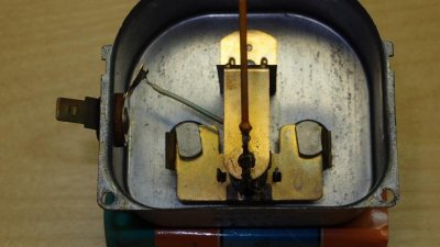
For your reference I attach a photo showing the 1967 Charger ammeter. :eek:ccasion14:
 

Attachments

  • PC241602.jpg
    PC241602.jpg
    39.6 KB · Views: 969
I just dug out an old 73 alternator gauge, and like your pictures, it is a pretty stout piece. I have to agree that it can handle quite a bit of current. Based on a very rough "eye measurement", it has to be equivalent to at least an 8 gauge wire. Bottom line is I agree that a well wired system using the original gauge can be done safely. Thanks for the pictures and continued input! :VB toast:

Also, as 72RoadrunnerGTX states: "The biggest advantage I see to a higher rated alternator isn’t so much the need for the max output current, it’s the improvement in alternator output at lower engine speeds, idle, as compared to the much lower rated stock units." I couldn't agree more. This is actually the primary reason I upgraded my system. From there, I also figured I would improve some other areas of my wiring.

One other item that has not yet been mentioned: This thread has so far discussed the power side of circuits (that fed by 12 volts). Too often grounds are neglected. People may spend a lot of time upgrading the power side of the system and do nothing with the grounds. A circuit has to travel through a ground as well. The ground circuit will carry as much voltage as the power circuit will - be sure to upgrade ground wires and connections as well!!!

Again, thanks for the continued input - hopefully this thread will be useful to others in the future so they can make wiring changes to their car!
 
This is a good post with good info for everyone. I actually bypassed my amp gauge on my 63 only because its 51 years old so I bypassed it and installed a voltmeter. I also agree with most said on here. Like many people think if they put a 100 or 125 amp alt on their car that it will burn the wires up. I tell them you could put a 500 amp alt (course you really wont) on the car as it will only put out what the cars load is and what the battery needs to stay charged. The volt reg will control the alt output to put out only what it needs.
And I also agree that most dont realize the amp gauge only measures the current going into the battery. You could turn on your headlights on high and the blower motor on high and turn on the AC and a rear window defogger and the alt may put out 50 amps but if the battery is charged the amp gauge will be in the middle or close to it as the alt output feeding the car loads will all be on the alt side of the amp gauge.

This post should go in some kind of technical archives or something like that to save it. Thanks for the good post , Ron
 
And for those who are afraid of a 100 amp alternator, remember that there's already a 800 amp battery in the system.
 
Any way to enlarge the schematic? My bi-focals don't get it................................MO
 
And for those who are afraid of a 100 amp alternator, remember that there's already a 800 amp battery in the system.

Very true. The same runs true for an alternator or a battery. It will provide current up to its capacity, but only what the circuit demands.

From a battery perspective, this is why a fusible link is so important. If you have a +12V wire touch ground for any reason, the battery will quite successfully use its 800 Amps to start welding that point. Don't underestimate the power of a car battery. It is NOT "just" 12 volts, it is the 800 Amps that are to be respected.

So as stated, the danger lies not in adding the 100 Amp alternator (or a massively powerful battery for that matter). It lies in trying to use a lot of that power through a wiring system that is not designed to handle the load. Be sure you protect individual circuits with fuses, and the overall feed with a fusible link. There are many ways to do this - but be sure to think through the overall circuit design so you can safely enjoy your Mopar!

- - - Updated - - -

Any way to enlarge the schematic? My bi-focals don't get it................................MO

Try right clicking on the schematic and copying it to your PC. Then your picture viewer should allow you to zoom in. If that doesn't work, PM me with your email and I will send you the schematic.

Hawk
 
Also remember the rating of the Alternator is rpm dependent too. There is a good tech article on comparing old tech to new tech. An older 50 amp alt may only put out 10-15 amps at idle, while a modern 50 amp alt can deliver 30-35 amps at idle. So the use of your car is also a factor in building a system. This idle factor is another reason that the 12 and 14 ga wires where ok even with the HD alternator installed. G
 
I mounted a starter relay in the trunk like the MAD setup. 8 ga power wire to distribution block on firewall. 8 ga wire with 12 ga fusible link to alternator.I will keep the original power wire to alternator hooked up too for now. I plan on coming from the distribution block to the original starter relay. What size wire and fusible link is recommended for that connection? I have a piece of 12 ga wire with 16 ga fusible link that I have laying around. Would that be sufficient or should I buy more 8 ga wire with 12 ga fusible link?
 
I mounted a starter relay in the trunk like the MAD setup. 8 ga power wire to distribution block on firewall. 8 ga wire with 12 ga fusible link to alternator.I will keep the original power wire to alternator hooked up too for now. I plan on coming from the distribution block to the original starter relay. What size wire and fusible link is recommended for that connection? I have a piece of 12 ga wire with 16 ga fusible link that I have laying around. Would that be sufficient or should I buy more 8 ga wire with 12 ga fusible link?

Hi Krowbar,

On a stock car, the fusible link only goes from the distribution block to the firewall and it powers the battery side of the under dash wiring. As you have seen, a fusible link is typically 2 gauges less than the wire that it protects (but that does not mean ANY wire 2 gauges less will work).

Since you have a relay in the trunk, I assume you are only then powering your heavy gauge cable to the starter in start mode and have it unpowered the rest of the time. I also assume the rest of your system is stock. The 8 ga wire to the trunk makes sense since you are going a longer distance. Also, since you are going a longer distance without protection from a fuse, adding a 12 ga fusible link makes good sense (and it should be close to the battery). The original wire from the distribution block to the starter does not have a fusible link. Since you are only going a short distance, I would just stick with a stock cable without a fusible link. The starter solenoid is powered through a 12 ga wire.

I hope I am understanding your system and questions...

Hawk
 
I ran 8 ga wire to a New distribution block with no fusible link. I then ran 12 ga fusible link at distribution block with 8 ga wire to alternator. Yes on the solenoid setup you questioned. On the starter relay wire that energizes the solenoid, where do I wire that into at the original starter relay on the firewall? Right now all wiring is original through bulkhead. I put a toggle switch inline on the ignition wire at the starter relay for a theft deterrent. Hope I'm making sense on my hook ups.
 
Auto Transport Service
Back
Top