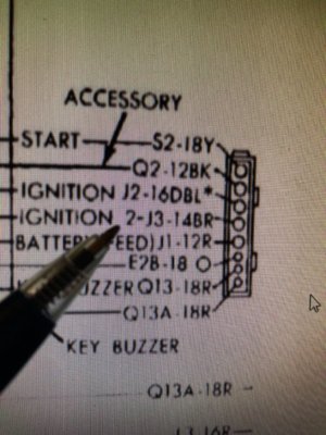
For clarification, the brown wire is identified as Ignition 2 in all factory technical info. The blue with tracer is ignition 1.
In post #4, you indicate a measured 500ma current draw with the key in the run position and 0 current draw in the off position. MSD? Are you sure the heat damage was not present prior to the MSD install?
Red wire shorted? Are you measuring resistance with a DVM at the dash harness ignition switch Molex? If so, you will measure grounds through any other unswitched loads on that circuit. If it was dead shorted, you would know it within a second or so after the battery is connected, there would be smoke somewhere.
You are using an out of date browser. It may not display this or other websites correctly.
You should upgrade or use an alternative browser.
You should upgrade or use an alternative browser.
Ignition 1 “Run” shorted?
- Thread starter Moparfiend
- Start date
Thank you 72RR and Nacho for working with me on this. I am trying to confirm all my fuse box connections which is proving difficult due to old wiring with splices and changes in colors etc. I understand that the light bulb will look like a short if switched on.
Below is the wiring I assume you are referring to. It does look like I am wrong and that you guys are right RE Brown is ignition 2 (start).
The guy who worked on my car cut the brown wire which obviously was drawing a lot of current and burned up. Then he ran a switched hot wire to the MSD box for "Run". Car starts with the column ignition switch as normal as long as the "run" is switched on prior.
So cutting the Brown wire should have disabled the ability to start from the column ignition switch. So I am thinking something was changed or swapped.

Nacho-RT74
Well-Known Member
I still can't imagine what happened to burn the brown wire... once again, that wire doesn't handle an ammount of current able to burn like that, and in any case just feeds while cranking. Rest of stages remains hot but without handling loads
matthon
Well-Known Member
I am probably a simpleton with diagnosing wiring issues, however, when you say the brown wire was cut, where was it cut?
If brown was 'start' and is no longer connected to anything, a new switched 'run' wire was connected to the MSD, which has to be switched 'on' to start from column, and car starts from column, wouldn't that mean there are 2 'run' wires?
Meaning, was the 'run' wire from the column used to power the 'start' wire on the other side of the connector. Not sure if that is even possible, wouldn't the starter stay engaged?
Do the wires match up on each side of the connector?
Hey 72RR do you remember if all the Power Ooke connectors were the same current rating? If so did you use the 30A connectors? Also did you buy a crimper? If co what do you use?Keep in mind, the Molex terminals at the ignition switch connector will build up resistance and create excessive heat under normal loads after all these years. The brown wire (ignition2)is the ballast resistor bypass and would only have coil current while cranking only. The measurement posted shows no load present on the brown wire at rest. The picture shows that most of the heat damage is at the red wire main power feed. Again, fairly common on these cars. Replace the Molex connectors with something that can handle the normal current loads.
These are Anderson Powerpoles, reduced the voltage drop on ignition1, while runing, by a full volt over the undamaged 48-yearold Molex connector they replaced.
View attachment 711467
Many Thanks
- Local time
- 11:06 PM
- Joined
- Jan 14, 2009
- Messages
- 2,297
- Reaction score
- 1,925
- Location
- Shoreline, Washington
There are three different terminal sizes that fit the PP housing, 15,30, and 45 amp. All will interchange, basically the wire size determines which to use. I used the 30 amp terminals on the 12 gauge ignition switch wires and 15 amp terms on the smaller 18-20 gauge wires, key buzzer switch. Some later factory ignition switch replacements used 10 gauge red & black wires, had to use the 45 amp terminals.
If you plan to use the Power Poles for other purposes, I have many times, recommend getting the correct crimp tool, will do all three sizes. I’ve installed them initially with other crimp tools that were close then soldered but ended up getting the correct crimp tool.
Careful, last time I ordered them, tried Amazon, I found there are now a bunch of knock-offs being sold as Anderson Power Poles. Get them from Powerwerx.
From Anderson info;
· 15 amp contacts are recommended for 20-16 gauge wire
· 30 amp contacts are recommended for 14-12 gauge wire
· 45 amp contacts are recommended for 10 gauge wire
Last edited:
So after thinking about my current set up I believe it all makes sense (except for the high current draw on the brown Ignition 2 line). Please correct me if you see something wrong here.
The MSD is wired to a switch to power. The brown is cut off from the dash I need to measure the voltages during start and run.
Since the MSD requires a voltage this it acts as a run/kill switch. I am not using a balast resistor.
Yellow is the starter line and is functional from the tree.
Not sure whats up with the brown wire yet.
- Local time
- 11:06 PM
- Joined
- Jan 14, 2009
- Messages
- 2,297
- Reaction score
- 1,925
- Location
- Shoreline, Washington
So with the MSD wired with the ignition sense lead connected to a switch, I assume the switch has battery voltage. The brown wire would not be used and should not be connected to anything in the engine harness. Where it would normally power the stock coil, via the ballast resistor. Have you verified the brown wire in the engine harness is not currently connected to anything under the hood? It should not have any load on it wired as described. I see in your post 4, you show it as being open?
Last edited:
I have not hunted that down but I will. Also if there is now no power on the other side of the switch then it would explain why it was abandoned. I would need to feed it 12V to eliminate the under dash switch. On the other hand a hidden kill switch has its merits. Will post what I find out with respect to current connections on that brown line.So with the MSD wired with the ignition sense lead connected to a switch, I assume the switch has battery voltage. The brown wire would not be used and should not be connected to anything in the engine harness. Where it would normally power the stock coil, via the ballast resistor. Have you verified the brown wire in the engine harness is not currently connected to anything under the hood? It should not have any load on it wired as described.
- Local time
- 11:06 PM
- Joined
- Jan 14, 2009
- Messages
- 2,297
- Reaction score
- 1,925
- Location
- Shoreline, Washington
"Car starts with the column ignition switch as normal as long as the "run" is switched on prior."
This indicates the switch works now? if so, it's getting power from somewhere.
Is it your intention to have the MSD system work from the stock ignition switch?
This indicates the switch works now? if so, it's getting power from somewhere.
Is it your intention to have the MSD system work from the stock ignition switch?
Yes car starts with key yes. The yellow start line is in the stock set up.
- Local time
- 11:06 PM
- Joined
- Jan 14, 2009
- Messages
- 2,297
- Reaction score
- 1,925
- Location
- Shoreline, Washington
The MSD needs power on the sense while cranking and in the run ign switch position. On a Mopar ignition switch, the ignition 1 (blue with tracer) is the run power for the ignition system. But it will not have power during the crank/start position. The brown wire (ignition 2, ballast bypass) will be powered up in crank only, goes dead in the run position. Like the yellow starter wire but separate.
To have an MSD work normally on Mopar, the brown and blue/tracer need to be connected together then connected to the MSD sense lead. All other brown wire connections need to be removed/isolated.
To have an MSD work normally on Mopar, the brown and blue/tracer need to be connected together then connected to the MSD sense lead. All other brown wire connections need to be removed/isolated.
Thanks 72RR! So the set up the way I have has a single switched 12V line to the MSD sense line in.
Now what I believe you are saying is that if I wanted to get the original tree set up working I would combine ignition 1&2 together to the MSD sense line. The brown ignition line needs to be verified so that I can try it. I’l see what I can do on that as I work on that area soon. I have to replace those crappy Molex connectors.
Now what I believe you are saying is that if I wanted to get the original tree set up working I would combine ignition 1&2 together to the MSD sense line. The brown ignition line needs to be verified so that I can try it. I’l see what I can do on that as I work on that area soon. I have to replace those crappy Molex connectors.
- Local time
- 11:06 PM
- Joined
- Jan 14, 2009
- Messages
- 2,297
- Reaction score
- 1,925
- Location
- Shoreline, Washington
Looks like a '70 horn relay.
Guy’s I successfully fixed Bubba’s electrical work with your help! Thanks especially to 72RR and Nacho for sticking with me on this! I ran the Blu and Brn wires together and totally rewired the connector. It works great! Thanks guys for everyone who helped me I am grateful to have you guys here! I will post some pics of how I decided to wire the Molex workaround.
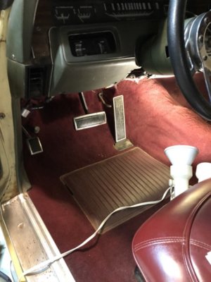
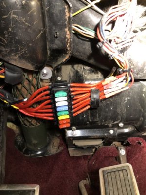
Here are a couple of pics to show what Path I decided to go to bypass the Molex connection. The order of the fuses are the same as the original connector. I know it will be a pain if I have to pull the ignition switch or column but its a new ignition switch and wires so I don’t anticipate any issues there for a while and the soldered connections are good and shrink wrapped. Oh and I got the fuse holders for $8. Now if there are any shots in the future I can isolate and teplace


- Local time
- 11:06 PM
- Joined
- Jan 14, 2009
- Messages
- 2,297
- Reaction score
- 1,925
- Location
- Shoreline, Washington
A word of caution, there is a reason why auto manufactures don’t fuse ignition system power supplies, fuses can fail or blow while the vehicle is in motion.
mopar 3 B
Well-Known Member
Fuse link can also go up in smoke. What would the ill affects of a fused ignition #1 circuit be? External lighting would not be affected (headlights and tail lights). All but wires going to actual engine functions are fused at the fuse box anyway.A word of caution, there is a reason why auto manufactures don’t fuse ignition system power supplies, fuses can fail or blow while the vehicle is in motion.
- Local time
- 11:06 PM
- Joined
- Jan 14, 2009
- Messages
- 2,297
- Reaction score
- 1,925
- Location
- Shoreline, Washington
What would the ill affects of a fused ignition #1 circuit be?
Just a possible sudden and unexpected loss of engine power, power steering, and power brakes, all possibly while in motion with little time for a reaction. The main fusible link is slow reacting and requires a very large overcurrent situation to open it up. Fuses are simple and cheap protection for other less-essential components and wiring but add another possible point of failure to any circuit. Headlamps are not fused as well for the same reason, uses an auto resetting circuit breaker built into the switch for wiring protection.
Last edited:
Similar threads
- Replies
- 7
- Views
- 1K
- Replies
- 15
- Views
- 1K
- Locked
- Replies
- 0
- Views
- 1K
- Replies
- 20
- Views
- 4K


