• When you click on links to various merchants on this site and make a purchase, this can result in this site earning a commission. Affiliate programs and affiliations include, but are not limited to, the eBay Partner Network.

Voltage drop of 2.8.

paladin06

Well-Known Member
Local time
1:30 AM
Joined
Jun 4, 2012
Messages
815
Reaction score
464
Location
East Valley AZ
I need help with a voltage drop of 2.8 from the negative battery post to the wall behind the VR. HELP. I've cleaned the junction box, replaced both bat cables, did the charging system mod, replaced the ignition switch.

With the key on and car not running I read 12.36 volts at the blue wire to the ballast resistor. At the blue wire from the ballast resistor it reads 11.75. Are these good numbers?
 
When the alternator is not turning you should get those numbers. Around 12 volts. Start the car and check the voltage between the positive and negative terminals of your battery. With engine running it should be between 13.8 and 14.2 volts. If your not getting at least 13.8 volts you have a problem. If it is more than 14.2 it is charging too much and can over charge the battery. Of course less than 13.8 won't keep the battery charged.
 
I get 12.32 at the battery with the car running. When not running I get 12.46.
 
I need help with a voltage drop of 2.8 from the negative battery post to the wall behind the VR. HELP. I've cleaned the junction box, replaced both bat cables, did the charging system mod, replaced the ignition switch.

With the key on and car not running I read 12.36 volts at the blue wire to the ballast resistor. At the blue wire from the ballast resistor it reads 11.75. Are these good numbers?

12.36 minus 11.75 isn't 2.8 volts. It's .61. Don't know why you would losing half a volt thru the ballast resistor.
 
The voltage drop test I was told to run is with the car running, put the neg lead on the neg battery post and the pos lead at the wall behind the VR. It should be .3 or less and I get 2.8.
 
I get 12.32 at the battery with the car running. When not running I get 12.46.

If your getting that with the volt meter leads, red on pos, black on neg. It's not charging. I would start by having the alternator checked. Most of the time that is the problem. Battery going dead?

- - - Updated - - -

The voltage drop test I was told to run is with the car running, put the neg lead on the neg battery post and the pos lead at the wall behind the VR. It should be .3 or less and I get 2.8.

Why are you doing that? What problem are you having?
 
Alternator checked and passed the test 5 times.

- - - Updated - - -

Not charging.

PS I have non steel spacer between my alt and engine block. The one on my 72 Duster is steel. Should this spacer be steel?
 
Every one I have ever seen is. I would think it would ground thru the bolt going to the block. But you can take a piece of wire and ground the case to see if it helps.
 
I forgot mopars have an external voltage regulator. you can bypass it and see if it starts charging. Unplug the regulator and ground the bottom left pin hole in the connector. Then start it up. Bring it up to a fast idle if it starts charging it's the regulator. If it doesn't I guess you start checking the wiring under the hood first to see if something is not connected. Could possibly be wire that burned in two. ( that happened to me on my challenger once).
 
you have a bonding issue between your engine block and the body
your regulator needs to see a good ground to operate the second brush in the alternator
 
you have a bonding issue between your engine block and the body
your regulator needs to see a good ground to operate the second brush in the alternator


The alternator, voltage regulator,battery & ignition switch have all been replaced. A bypass of the ammeter was also done.....


Need to learn the charging path by using the wiring diagram for you vehicle...Path goes through the Ignition switch,ampmeter, to the starter relay, fusible link, regulator , alternator, battery to ground.....

Since the car, starts I confidant the wiring is good from the battery to the ignition switch....... The starter circuit includes the wire out of the ignition switch, from the battery to the starter..... The power to the ignition switch from the battery.
I would check path of the blue wire from ignition switch to starter relay fusible link to regulator.....
 
With the switch on and the car not running I have 12.35 volts at the blue wire to the ballast resistor.

The alternator, voltage regulator,battery & ignition switch have all been replaced. A bypass of the ammeter was also done.....


Need to learn the charging path by using the wiring diagram for you vehicle...Path goes through the Ignition switch,ampmeter, to the starter relay, fusible link, regulator , alternator, battery to ground.....

Since the car, starts I confidant the wiring is good from the battery to the ignition switch....... The starter circuit includes the wire out of the ignition switch, from the battery to the starter..... The power to the ignition switch from the battery.
I would check path of the blue wire from ignition switch to starter relay fusible link to regulator.....
 
IGN switch supplies switched power to the coil resistor, the regulator IGN terminal, & the blue field wire on the alternator 12V, or 14V when running

Mechanical regulator had two wires going to it: a blue ignition-on wire feeding it juice & a green wire going from the regulator to the single-field plug-in at the alternator.

at the bypass for ammeter....You have a splice connection .....The black wire from the bulkhead connector to the welded splice & ammeter & the red wire returning back to the bulkhead connection... look for blackenedconnection, with heat damage..
check & see if problem lies there...

Here a few video’s from Mopar C dockbody

http://s51.photobucket.com/user/68Cbarge/media/MAd wiring tech/MADwiring017.mp4.html
 

Attachments

  • Page10.jpg
    Page10.jpg
    134.4 KB · Views: 269
  • Page09.jpg
    Page09.jpg
    141.3 KB · Views: 291
  • Page08.jpg
    Page08.jpg
    155.7 KB · Views: 255
  • ign sw graphic_img_2548.jpg
    ign sw graphic_img_2548.jpg
    44.9 KB · Views: 296
Last edited:
Out comes the dash pad and instrument cluster after breakfast.

Thanks

- - - Updated - - -

Let me try to explain something that happen last week and I hope it makes sense.

While trying to solve this charging issue I have been checking/replacing wires under the hood and dash. At one point I started the car and for the first time it read 14.3 volts at the battery. I removed the green wire from the VR and it went full field.

I hooked all back up. Started the car again and everything was working fine. I turned on the lights, the stereo then I high beam floor switch and the starter spun up. Scared the crap out of me.

I immediately turned everything off including the car. Looked under the hood to check the starter for a possible short and all was good.

Started the car again, high beams hit and the starter spun up again. I turned it off. Check for anything I could see under the dash that might be wrong. Move around a few wires, unwrapped as much as I could. All seemed will started the car again and it was back to the NON CHARGE situation but the voltage at the battery would increase from 12.33 to 12.36 if I raised the RPM's.

Took the alt to the shop for test and it was good. Put it back in the car took the car to the shop for a system test, it passes but showed a low VR volts. That's where I am today.
 
quoting 440 roadrunner ffbo member.......
BULKHEAD CONNECTOR

But there are several problems with these old cars

PLEASE read the Mad article I posted.

Here's how your headlight power works

Because you now jumpered the charging line, you now have TWO wires essentially in parallel supplying power INTO the car through the bulkhead

These conductors are the original wire from the battery -- starter relay - fuse link - through the bulkhead - to the ammeter

The second one is now battery --your new jumper wire-- from the alternator -- through the bulkhead -- to the other side of the ammeter

(It would be BEST to disconnect the ammeter and jumper these two wires together IN CASE the ammeter has developed a problem)

NEXT coming off one side of the ammeter is the IN HARNESS SPLICE

From this splice is an UNfused wire going directly to the headlight switch, and the swtich has a breaker built into it

THIS WIRE ONLY SUPPLIES the headlights, NOT the tail / park and instrument lights which comes off a separate fuse

With the switch on, headlight power next goes to the DIMMER SWITCH and either hi or low beams is selected, the power then goes out through the BULKHEAD CONNECTOR to the headlights

So the problem could be a damaged BULKHEAD CONNECTOR, IN HARNESS SPLICE, LIght switch CONNECTOR, the LIGHT SWITCH itself, a bad DIMMER SWITCH, back OUT through the BULKHEAD CONNECTOR, and of course, last, problems right AT THE HEADLIGHT CONNECTORS including the GROUND at the headlights, as the lights are grounded from a pigtail coming off the headlight connectors.

This is one of the easiest circuits to check out. I usually start with the dimmer switch because it's easy to get to.

First, take a good look at your HIGH BEAM INDICATOR. Power for this indicator comes directly off the hi beam side of the dimmer switch. If you are NOT getting power there in hi, then the trouble is on the INTERIOR side of the car, most likely. This is assuming other accessories operate normally, such as radio, heater, wipers.

Take a meter/ test lamp and probe the dimmer. You should always have two terminals hot, as this is a simple double throw switch -- one terminal gets power from the light switch, ONE of the other terminals feeds power to the lights.

If you have no power to the switch, you have no choice but to access the light switch.

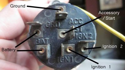
You know how to remove the switch? THAT is a little trick. Unhook the battery ground, reach up under the dash, and feel for the release button on the switch. Pull the **** out as far as it will go with one hand, push the release, and "fiddle" a little with the **** and release until the **** and shaft comes outFrom there it's a matter of inspecting the connector for melt/ heat damage or corrosion, and determine if the switch has power or whether the switch has given up.
 
The dimmer switch wires were tapped together when I got the car, just as the ammeter wires were.

I completely removed the old ALT power wire when I did the ALT to SR and BATT to SR mod.

Here I am confused. I don't have "The second one is now battery --your new jumper wire-- from the alternator -- through the bulkhead -- to the other side of the ammeter..

I ran a wire from the ALT to BAT post on SR and from Batt to BAT post on SR per the mod.
 
check the regulator ground. Engine Rmp1500, put one meter probe on the battery NEG post, & the other probe on the regulator mounting flange..... you want LESS than .2V ---- More means you have a ground problem between the battery, the block & the body of the car, & the regulator.
 
Yes as noted before I have like 2.4volts.

check the regulator ground. Engine Rmp1500, put one meter probe on the battery NEG post, & the other probe on the regulator mounting flange..... you want LESS than .2V ---- More means you have a ground problem between the battery, the block & the body of the car, & the regulator.
 
How much area of bear metal do I need at the VR bolt points?

- - - Updated - - -

What the hell is a start washer?
 
Auto Transport Service
Back
Top