• When you click on links to various merchants on this site and make a purchase, this can result in this site earning a commission. Affiliate programs and affiliations include, but are not limited to, the eBay Partner Network.

What is my Ammeter telling me

LowBikeMike

Well-Known Member
Local time
3:11 PM
Joined
Nov 28, 2020
Messages
391
Reaction score
430
Location
St Louis, Mo
1969 Road Runner 383 4 Speed, Factory Air, previous owner converted to 1 wire Alternator. I cannot find any markings on Alt, but I can see what appears to be an external regulator attached to the back. The case is grounded to chassis. Single wire from Alternator runs directly to Ammeter. Connection at bulkhead has been eliminated, connector wallowed out and wire ran straight through to meter. Other side of meter is connected to splices and back out to starter relay via fuseable link. Battery resting voltage is 12.5 volts, starts easy, no hard crank, runs good. So, here is Ammeter behavior

When starting Ammeter needle doesn't move. After start up, voltage reads 14.5v and Ammeter midway to Charge side. Voltage and Ammeter stay consistently with those reading during normal driving with no Accessories on. Turn signal, drops voltage a few tenths, and Ammeter fluctuations with each blink. When I turn the AC on, Ammeter goes further to Charge indicator and voltage drops to 13. 6, car still runs fine, increasing fan speed moves Ammeter further to charge and voltage drops a bit more. With AC on or heavy load, Tachometer reads low, no other working gauges to judge. At idle, voltage will drop to 12.5 and below sometimes

A couple of things are bothering me. 1. Am I loosing voltage due to an underpowered Alternator, 2. Why am I not seeing a discharge when cranking (I see a discharge with key off, headlights on,but not with key on and any other Accessory turned on and engine not running) 3. Is my tach inaccurate during high load, because of low voltage (Mallory Unilite Ignition).

What are your thoughts.
 
Sounds about right to me.
My amp gauge bumps with each turn signal flash at idle.
I have never paid attention to my gauge when cranking but I guess the alternator is turning generating current but could be completely wrong on that.
 
During cranking all the power goes from the battery right to the starter. So the ammeter is essentially not part of the circuit.
For the most part your description is normal.
The 2 wire field with a solid state regulator do charge better at lower rpms.
 
There is something wrong. When turning in AC it SHOULDN'T read charge. If reads charge is because there is load going to the batt and thats wrong. Load running to batt it must be just to recharge batt.

Depending in alt capacity and engine speed, it COULD read charge just if batt lost load previouslly and alt is able to feed EVERYTHING working on car PLUS an extra load to the batt being recharged JUST if as mentioned previously battery lost some load

Starter motor is directly hooked up to the batt, and this load is not registered into the ammeter reading. BUT after crank up, the ammeter will register the load lost by the cranking job coming back to the batt, as far alt is able to recharge it.

In one word, the ammeter is a batt gauge which will tell you when batt is being discharged and when is being recharged. As far batt is completelly charged and alternator is able to source ( correctly sourced on alt side ) everything on car, the ammeter will register ZERO ( centered needle ). That's the perfect status.

Of course after some discharge moments, the charge reading will be normal and more less proportional ( on time and intensity ) than the previous discharge reading, untill batt is on its normal charge status. So if you give brakes and get a small discharge reading, when reving up, more less same reading will be obtained but to charge side. This happens with any device you activate. Time and intensity on charge stage varies depending on alt capacity at certain speed.

Of course, while more capacity alt you are running, less power from battery will be requested because alt will be able to source it, so less flickering at ammeter will be read.

I can give you dozens of threads about this, but let's start with this

https://www.forbbodiesonly.com/moparforum/threads/poll-about-ammeter-reading.198930/

My explanation ( diagrams included ) begins at page 3
 
Last edited:
I agree with Nacho. It sounds like the alt output for the one wire alt is wired to the wrong side of the ammeter. And it also sounds like its not charging right. Get a votlmeter and ammeter test meters on the car and see just what amps the alt is putting out and what the voltage does at that time. Even if the alt output is wired on the wrong side of the ammeter the voltage should not drop way down unless its only like a 35 or so amp alt which I dont think it is being a modern one wire alt and it would only drop at idle with all acc's on. Do you have a seperate volt meter in the car ? What is the amps rating on the alt and what amps is it putting out when all this is going on ? Ron
 
Thanks for the replies. Yes, I have a seperate volt meter wired in to watch what voltage is doing, I will have to grab an inductive Ammeter and see how many Amps are actually being generated. I've looked on the Alt and have not been able to find any information, but I have not removed it yet for a better inspection. I re-read Nacho's previous post and it all makes sense, so I am tracking with you. The obvious thing I see is the previous owner wired the Alt directly to the Ammeter instead of to the interior loads (ignition, lights, fuse box) and those components are wired directly to the battery via the Starter relay junction. Would that be one of the things causing the Ammeter to read that way it does? Also, I don't suppose simply switching the wires at the Ammeter likely have much impact?
 
Yes... you are reading opposite to the factory setup and specs. When you get a charge reading with everything wired like that, the load is moving to charge side because the load demand is on battery side. While is correct the load is going on that direction, is not correct all the load is actually charging, but supplying the power to the accesories hooked on that side. This causes a lot of unnecesary stress to the factory ammeter and even more to the bulkhead on BOTH wires cavities ( red and black ).

The perfect situation will be keep the load on alternator side. On this way you will actually know how much of the load is getting charged or discharged the batt according tonthe batt status.

As far the alternator is able to feed everything, it means your battery is safe so you won't have a battery discharge stage, so zero load going throught the ammeter. But on a reading like the one you are getting, you actually don't know the battery status. It may be charged or not.

After this, some nice upgrades will be adviced at least coming from me, like a parallel alt wire between ammeter and alt, to take out some ( or all ) of the load from the bulkhead path, saving from overheat that spot. But IMHO, if you want to keep the ammeter, I would make it read correctly first wiring it correctly, clean all the spots, and check furtherly the ammeter gauge. The ammeter is a gauge hard to beat BUT After 50+ years of abuse ( underrated alternators, incorrect spot on sourcing acc ), sure a nice check would be mandatory.
 
Ok. Your advice and reading the schematics gives me a better picture of the issue and correction required. The thing I don't seem to have to worry about short term is the bulkhead, since the previous owner eliminated the connection in the bulkhead and ran the wires straight thru the wallowed out bulkhead to the Ammeter and splice.
 
Other side of meter is connected to splices and back out to starter relay via fuseable link.... The obvious thing I see is the previous owner wired the Alt directly to the Ammeter instead of to the interior loads (ignition, lights, fuse box) and those components are wired directly to the battery via the Starter relay junction.
Splices? As mentioned, there should be no vehicle loads of any kind on the battery side of the ammeter, this includes anything directly connected to the battery. All vehicle running loads need to be on the alternator side of the ammeter. Any loads present on the battery side will register as charging current on the ammeter and defeats the purpose of the ammeter.
Better off keeping the bulkhead by-pass on the charging circuit wiring, by far the weakest link in the original design.
DSC09071r.JPG
 
Last edited:
Thanks for the picture, it is incredibly helpful and gives me an idea of how to correct the spliced side without much effort. Based on your picture, should the inboard side of the Ammeter be attached to the Alternator lead
 
Pictured is a ’72 rallye cluster, not sure for the ’69. However, the cluster frame casting should have a “RED” labeling casted near one side of the ammeter mount, red would be the battery side.

Found a pic.
road runner cluster.jpg
 
Last edited:
My connections at the Ammeter are correct, its everything in between thats a bit messed up.
 
Getting ready to tackle rewiring properly and have a simple question. I suppose the piece between the two Ammeter terminals show in the above pictures is a simple insulator? Mine is pictured below and appears the previous owner just insultated each terminal seperately with a non conductive washer. Anyone see any issues with this set up?

20210806_074416.jpg
 
That should work, but remember, there is also an internal insulator as well.
 
two details:

-yes it will work as far is heat resistant! A regular plastic washer could not work. Masonite, baquelite will work. Sometimes depending on your load requirements and your alt capacity it can get hot. This becomes critical IF the ammeter internally is already affected by earlier abuses. Tipically the charge unbalance cause by the factory alt rate makes the internal shunt to get stretched by the excesive load going throught. This also makes to get loosen the studs from the internal shunt causing a bad contact hence a resistance, so more causes to get hot.

-As mentioned, The ammeter gets also an internal isolation. If the exterior one got damaged the internal could be on similar conditions.

some more info about how are the ammeters and the "weakening" of them

https://www.forbbodiesonly.com/moparforum/threads/dissection-and-study-of-a-mopar-ammeter.199179/
 
Last edited:
Anyone see any issues with this set up?


Yes, potential issue, the original insulators are “keyed” into position at the slots at the end of the insulators. There are tabs cast into the inside of the cluster frame the slots fit over the tabs to maintain the ammeter stud positions passing through the center of the frame holes, preventing contact with the frame. If the inner insulator has also been replaced or in poor condition, the studs would have to have insulating sleeves of some kind to ensure the studs are fully insulated from the frame.
 
Thank you for your answers and guidance, its really helpful. Not sure for how long, but the car had been running with its current electical hookup (load on wrong side, Ammeter backwards, etc) before I purchased the car about a year ago, and I have since put about 4,000 miles on it with no issues and have been cleaning up other wiring issues. That being said, I know issues can crop up anytime, but I think the Ammeter terminals are isolated from the base and heat has not been an issue...yet. I'm going to wire the load up properly to the Alternator side for now, and address the situation further when I get the rust and paint fixed. Its obvious to me the cluster has been apart, since it has a tach and does not have the tach wire divot punched out on the firewall. Heres a few pics of the car for those that like pictures. Yeah, I know its the wrong color, from what I can tell it was a nice Jamacian Blue from the factory and will be going back to that color.

20200904_131354.jpg 20200904_131404.jpg
 
@72RoadrunnerGTX
I don't think the replacement of the keyed insulation with a more "generic" one will be a huge deal, as far we are sure the ammeter is propperly isolated and sat in place, inside and outside... aaaand with the propper material. ( this is just an opinion ). But of course, since the correct isolator is available as repro for a couple of bucks, I think is better to keep it like factory did!

@LowBikeMike
Electrical parts on our cars use to be the more underestimated area thinking will live forever, will never fail and usually with poor adds on, fixes and a lot of hacking jobs. Sooner or later your car will demand a deep check on on every wire. Usually the electrical is the cheaper area to fix preventing any major failure, but is true it needs some patiente. Sometimes a correct $5 fix job with 3 or 4 hours invested on time will save a $500-1000 spend later with 6 or 7 hours invested.

Not just the years affect on our electrical parts, but the unknowledgement of owners and those so called "mechs" or "techs" ( hence the hack jobs )
 
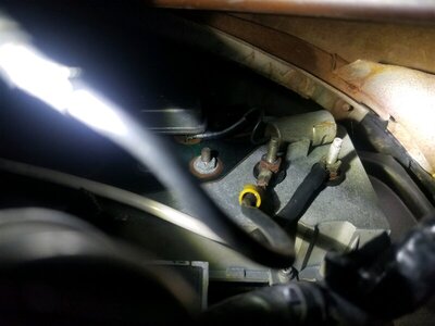
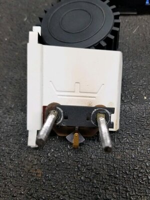
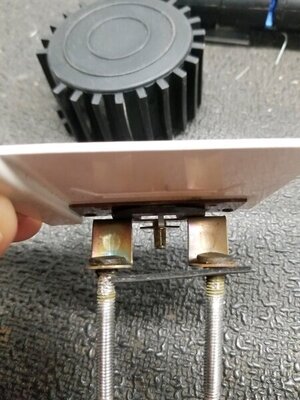
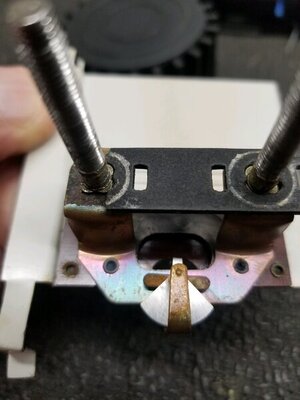
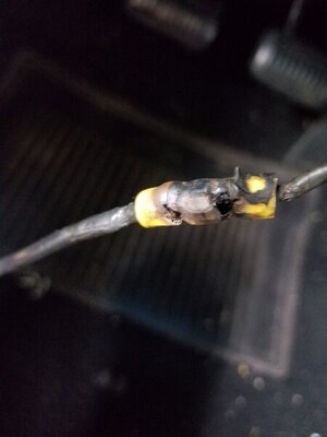
Started working on making the wiring corrections and one thing led to another. Stud on "red" Ammeter connection was turning when I tried to remove the nut securing the ring terminal so I stopped and reevaluated. Ended up just cutting the wire off the terminal with thoughts of attaching to the Alt side of Ammeter and just bypassing the Ammeter for now. Upon inpection of the black wire from main splice I found evidence it was melted against a red wire in the past and also found the wiring "correction" made by previous owner was heavily damaged, so I made the decision to pull the cluster. Original harness has LOTS of splices so I will be replacing it. Took gauges apart and found Ammeter insulator inside cluster damaged, heat discoloring on gauge bar and studs loose. The studs do not turn, but are loose. This leaves me a few questions.

As mentioned earlier, bulkhead connections have been bypassed by previous owner by way of drilling out connector and running wire straight thru, so no load on bulkhead. Could the improper connections (load on battery side of Ammeter) cause the heat that damaged the wire pictured (this is wire from main splice to Ammeter that was on the battery (wrong) side) after the earlier fix? Ammeter looks okay, should I be concerned about studs being loose? Anything else you see that I should be concerned with?

Thank you.

20210812_074649.jpg 20210812_074711.jpg 20210812_074702.jpg 20210812_074746.jpg
 
Also, were do you find the gauge insulators? I see Premium dash decals has them in stock, but I'm not crazy about $29.99 shipping on a 50 cent part.
 
Auto Transport Service
Back
Top