• When you click on links to various merchants on this site and make a purchase, this can result in this site earning a commission. Affiliate programs and affiliations include, but are not limited to, the eBay Partner Network.

Bypassing resistor

Stewsta

Well-Known Member
Local time
1:18 PM
Joined
Aug 8, 2012
Messages
184
Reaction score
20
Location
Enid, ok
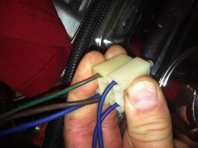
I have a new electronic ignition harness and need to bypass the resistor for FBO install. It's set up for a 4 pin ballast resistor and I can't find any info I can understand. One connector has 2 blue wires which have power in the on/ run position and none at start. The other connector has a blue and brown wire with power in start position and a red/green wire that is not used. If I'm understanding correctly I connect the blue and brown wires to one of the blue single wires. If that's correct which one? Thanks and I know this is all over internet but nothing is explained in stupid enough terms for me to understand with confidence. Stew
 
I would never guess the wiring of a 40 plus year old car so you'll need to check everything with a voltmeter, but basically you want to connect the run, start and positive field wire going to the voltage regular to feed the module. It's my understanding that the blue wires are all connected from the factory to power the coil (from the ballast) and alternator field circuit and are controlled by the ignition switch. Do you a wiring diagram for the FBO, might be easier to figure out. Ed
 
No directions. Simply states to bypass balast resistor. I think I'm over thinking it. If I just connect the opposite sides of balast resistor your done but that seems too easy.
 
Last edited:
No directions. Simply states to bypass balast resistor. I think I'm over thinking it. If I just connect the opposite sides of balast resistor your done but that seems too easy.

That's exactly how it's done - just connect one end of the ballast resistor to the other. It was only there to lower voltage to the coil during run mode, but it was bypassed during start mode to supply full voltage during startup.

http://www.moparmusclemagazine.com/techarticles/body/mopp_1110_ballast_resistor_guide_ballast_blast_off/
 
HT413- is there any reason why i would jump the other blue wire to the red/green wire when it's not used? Could I tie into that blue wire and run it to electric choke?
 
Yep, pull the resistor and connect the wires all together.

What you have now:
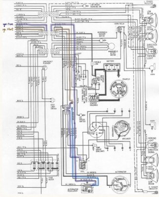
Right now you have a brown and dark blue connected on one side of the resistor. Brown is the ignition start circuit from the ignition switch. On start, it is hot and brings current to that dark blue, which goes straight to the coil, bypassing the resistor.

During run, that brown is dead and the dark blue on the other side of the resistor is hot. This dark blue comes from the voltage regulator and is spliced in with the dark blue tracer that comes from the ignition switch (ignition run circuit). It feeds 12v to the other side of the resistor, the resistor knocks the voltage down, then brings power to the dark blue (and the brown) and then to the coil.

If you connect them all, all it means is the dark blue that goes to the coil (now the electronic box) gets full 12v both in run and start. Technically, this allows you to cleanup a wire or two if you so desire, but really, just connect them all and move on unless you have some other charging issues, etc.

- - - Updated - - -

Now, this is a 69 wiring diagram, but from what you describe, you have the same setup.


image.jpg
 
Going to try this on my 72 340 Duster first. My 69 road runner still has a points system but not for long. I'll give it a shot today and thanks again.
 
HT413- you mention tieing the 3 blues and 1 brown all together, correct? FBO offers a jumper for bypassing the resistor and it appears that it only requires the one jumper which would be for the brown and blue connected wire and its respective blue on the other side. The red/green wire and its respective blue on the opposite side plug into the resisitor as normal leading me to believe that they arent needed since the red/green wire has no pin on the ignition box. Im confused. And thanks for the wiring diagram. Its a little blurry and i cant quite make it out clearly
 
HT413- is there any reason why i would jump the other blue wire to the red/green wire when it's not used? Could I tie into that blue wire and run it to electric choke?

Not sure off hand what your red/green wire is. What year / model car are we talking about?
 
That's a fine place to connect your electric choke wire, but just double check how your choke works first. I believe they all require constant 12v while the engine is running, so if that's the case for yours, then this is a great spot, nice and close to the carb.

- - - Updated - - -

Please provide a link for the jumper.

I simply replaced my ballast resistor with a large gauge wire and soldered both sides together. Sorry no picture, but you get the idea.
 
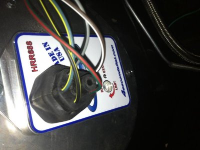
66 coronet. MH electronic harness. The red/green runs to the ignition box but there's no pin for it on the ignition box.

http://www.4secondsflat.com/Ignition.html

View attachment 162237View attachment 162236

Dang, just lost my original post...

ok, that makes sense now. That reed/green wire wouldn't be there in the oem 66 harness, but would be there in like 1975 or so. Sounds like that M&H is a bit of a one size fits all if I'm understanding you right.

The way a 66 is supposed to work (everything 74 and before I think), is a 2 prong resistor. 1 prong had a blue, the other has brown and blue. Connect those together and you're done.

From what you are saying, that red/green is not used, but I have no experience with that piece or that harness, so I don't want to steer you wrong here. Maybe contact M&H to be sure or perhaps someone else might chime in here?

We can keep trying to trouble shoot it as well. First, did the car run before y tried to upgrade the ignition and bypass the resistor?? If so! where did that red/green go to before?
 
Everything in the engine bay is new to the car so it has never run before with this harness. This resistor thing is the final hurdle before first start tomorrow.
 
Got a wiring diagram with that harness? Post it and I'll go through it with you.
 
Well there ya go. I've used 440roadrunner's advice before from mopar forums, seems like he knows what he is talking about. Glad you found the solution.

Enjoy! And post some pix / videos of her running.
 
Auto Transport Service
Back
Top