• When you click on links to various merchants on this site and make a purchase, this can result in this site earning a commission. Affiliate programs and affiliations include, but are not limited to, the eBay Partner Network.

Rewire front side marker to flash opposite front turn signal on 71-74 B Body anyone?

Dibbons

Well-Known Member
Local time
2:44 PM
Joined
Nov 29, 2014
Messages
5,031
Reaction score
6,059
Location
La Paz, B.C.S., Mexico
I like the way my '96 Dodge Dakota front side markers switch over to flash when I use the turn signals. They flash on when the turn signals flash off, and vice versa. Anyone know an easy wiring trick to accomplish this on a 1972 Plymouth Satellite?
 
Don't think it will be too easy unless there is something already available on the market.

You have to manage multiple states for marker light state on/off, turn signal on/off, and marker light in use and turn signal in use. When the running lights are in use, marker lights stays on when the turn signal is in use and in the off state and to turn off when the turn signal is in use and in the on state. When the marker lights are not in use, marker light turns on when turn signal is in use and in the off state and turns off when the turn signal is in use and in the on state. Marker lights stay on when in use and blinker is not in use. Marker light stay off when not in use and blinker is not in use.

Once you have this mapped, should be easier to see how the circuit can be built with various relays. Hope I got that right.
 
Fairly easy, two single pole double throw relays, one for each side. Connect the relay primaries (85 & 86) to ground and the turn signal circuit, relay activates when flashing. Run the side make light circuit through the relay’s secondary normally closed contacts (30 & 87A), power to the side maker is interrupted while the turn signal is flashing.
 
That sounds easy. My knowledge is generally limited to changing bulbs and chasing down a short or broken wire. The only thing I don't understand is the terminal names by numbers 30, 85, 86, 87A. Are they the same as terminals COIL, COIL, COM, and NO, and NC that I saw on the internet.
 If so, if the relay has five terminals (COIL, COIL, COM, and NO, and NC) is one left unconnected? One more question, what ampere rating relay is indicated? Thank you. (I just found another diagram, I assume it is terminal 87 that is not used, but still wonder about amperage rating)
Common “Bosch” style automotive relays are labeled 85 & 86 for the primary coil leads, Secondary contacts; 30 is C (common), 87 is NO (normally open), 87a is NC (normally closed).

- - - Updated - - -

Check this out, it sounds too easy.

http://dsl.torque.net/images/Markerflash.pdf

You would have to isolate the ground on the marker from the body somehow
Drawback with wiring the side marker as shown above is the ground for the side marker bulb comes through the turn signal filament, voltage drop through the turn signal filament will dim the side marker light some. A failure with the turn signal bulb will cause the side marker light to fail.
Doable however, as the ’72 side marker bulb socket doesn’t ground through the side marker housing.
 
aren't C body turning switchs attached with extra plug for "cornering" lights ? if thats what they do?
 
That sounds easy. My knowledge is generally limited to changing bulbs and chasing down a short or broken wire. The only thing I don't understand is the terminal names by numbers 30, 85, 86, 87A. Are they the same as terminals COIL, COIL, COM, and NO, and NC that I saw on the internet.
 If so, if the relay has five terminals (COIL, COIL, COM, and NO, and NC) is one left unconnected? One more question, what ampere rating relay is indicated? Thank you. (I just found another diagram, I assume it is terminal 87 that is not used, but still wonder about amperage rating)
Just noticed the last questions, Yes, 87 (NO) would not be used, Most common "Bosch" style automotive relays are rate for 15-20 amps for the contacts, more than enough the handle the side marker bulbs.

- - - Updated - - -

aren't C body turning switchs attached with extra plug for "cornering" lights ? if thats what they do?
The C-body cornering lamp system is separate from the turn signal circuit. It provides for a constant left or right cornering lamps while the turn signal is active in the corresponding position. C-body turn signal switches are occasionally marketed as replacements for some B & E body Mopars, can be identified by a second three wire pig tail & connector. Will fit & work, just no need for the extra leads.
 
Oh ok, is just to add more ilumination to the side you are turning.

MMM well, that could be used as a trigger to cancell up the sidemarking and allow the turning signal on same filament... right ?

( Something like that, thinking on relays &/or transistors and add wiring to each corner )

- - - Updated - - -

aaaand would need to be linked with front turnings, since rears are also brakes, and we don't want to turn on side markers with brakes

- - - Updated - - -

I already got how to do it with one relay on each corner and existant turning switch ( not the cornering one ), BUT just would work at night with parking lights on... have to figure it out how to make it work on day light.

to make it work at night and one relay on each corner

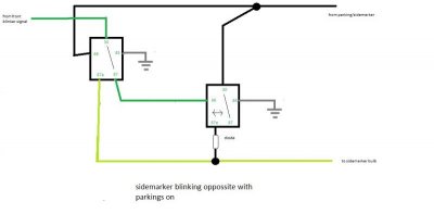
30... positive originally sourcing the sidemarker bulb
87A... feeding the positive sidemarker bulb
85... Ground
86... trigger coming from FRONT turning lights network
87 unused

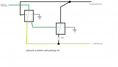
THIS will make turn off the sidemarkers while turning lights are lighting on the bulbs, making the "opposite" blinker function, but won't light up side markers as blinkers when parking lights are off ( daylight )

- - - Updated - - -

Ok just noticed was already told LOL

Fairly easy, two single pole double throw relays, one for each side. Connect the relay primaries (85 & 86) to ground and the turn signal circuit, relay activates when flashing. Run the side make light circuit through the relay’s secondary normally closed contacts (30 & 87A), power to the side maker is interrupted while the turn signal is flashing.
 
Good point. That's why these forums are so populated, each answer stimulates another slew of new questions and that's what makes life interesting, nobody has all the answers. I'll have to study up a Dakota wiring diagram now to get to the bottom of this.
 
The short answer would be to copy your tail lights for example, you would need to change the socket plug to a two pole one and switch bulb to a two pole one like in your tail lights, then if you had fender mounted signals or front signals in the bumper then just tap a wire from there to the new pole on the new socket. piece of cake.
 
I have a 94 Dakota and an 88 Dodge Shadow, on both vehicles side markers blink with front lights, and opposite blink when parking lights are on...the circuit is controlled by the turn signal switch itself inside the column
 
lets see what you think using dual relays on each corner ( despiting the PDF posted if you get some dimming deal )

sidemarker blinking parking on.jpgas turning light parking offf.jpg

- - - Updated - - -

The short answer would be to copy your tail lights for example, you would need to change the socket plug to a two pole one and switch bulb to a two pole one like in your tail lights, then if you had fender mounted signals or front signals in the bumper then just tap a wire from there to the new pole on the new socket. piece of cake.

sounds nice but... does exist dual filament, dual contact bulbs to sidemarkers bulb size ?

then, rear sidemarkers can't me tapped from rear blinkers, since they will turn on when braking. Needs to be tapped from fronts anyway ( bulkhead or turning switch itself )

- - - Updated - - -

NEEDLESS TO SAY, all flasher will need to be Heavy duty, due the added bulb loads. ( really HD on hazzard, if you have dual rear turning on each side )

- - - Updated - - -

My suggestion is using a regular and cheap relay system, which is actually a logic circuit, the basics for COMPUTERS and binary codes LOL.

MAYBE does exist some trasistorized micro circuit or chip already build to make that, BUT mostly sure will require at least one relay on each corner to hold the bulb load even being small to a sidemarker ? dunno. I just know some electricity, but not electronics
 
sounds nice but... does exist dual filament, dual contact bulbs to sidemarkers bulb size ?

then, rear sidemarkers can't me tapped from rear blinkers, since they will turn on when braking. Needs to be tapped from fronts anyway ( bulkhead or turning switch itself )


Oh no I m not saying tap to your rear lights lmao that would be silly, tap to your fronts or like on my 69 I have the A01 light group which has fender mounted turn signals and front bumper turn signals. and yes you can get dual element bulbs the size you need for side markers lights just switch connectors to a dual one and run the tap. But hey if you want a bunch of relays and wire harness mess have at it lmao.
 
if dual element bulbs exist on sidemarker size then everything is done, just add extra wiring tapped from turning signal and change sockets... maybe some mod on sidemarker housing to accept the new socket. No need for relays or whatever. Of course will work just like the front &/or rear parking lights, which with those TURN ON on parking, will blink over the existant fillament. If you want oppossite blinking tuning off the parking signal, will need relays anyway, just like the diagram I posted... but as mentioned will blink opposite just at nights
 
If I was to do this I would use two relays and a diode
one to break the ground when signal is on the other a delay off to supply power when the running lights are off and the diode
so you dont feed back into the sytem
 
I have trying to make a diagram showing what you said, breaking ground, but I can't find what you meant. Ground is common for both signals AND if you break it while is flashing, the blinker on sides will never light up, since you will be breaking ground also when you are sending the positive signal from blinker. So in one stage the flasher breaks positive, ground is closed, on next stage blinks on and ground is open.

UNLESS you feed with positive from batt on all corners and sidemarkers won't be feeded ever from flashers to blink, just sued as trigger to break ground. More wiring involved... and probably a 3rd relay ? have to think about.

I had tired last night to think more about
 
To make it flash opposite to the blinker you need to isolate the ground to the marker light so it will turn off when the blinker turns on using a normally closed relay and the delay off relay supplies power when running lights are off and the diode stops power going to the other lights
Bruce

That is per side so 4 relays or if you can find a electronics guy he could do it with transistors


after thinking about this it can be done on the hot side as well but same number of relays
 
Last edited:
ok, with a relay system and keeping it basic as posible there is no way to make turn on opposite at day light when blinking because at the time the bulb SHOULD being turning on by the flasher, you are triggering the relay to turn of the ground, so will never blink on... for one or another reason bulb will get cut negative or positive.


The only way to make it is adding an extra constant positive source to keep the positive source ( diff from the flasher source ) which will feed the bulb at the same time you are blinking and triggering the relay by ground. An of course mostly sure some more relay around.

That's why the opposite blinkering works with parking lights on ( per diagram I made ), because the positive is being sourced by this network, not the blinkering wiring. Blinkering wiring will be feeding just at day light.

But is true, mostly sure some electronic guy could do it by pre designed chips, instead use basic relays

I know Mercedes Benz use several kind of relays with more prongs around ( 6 and even 7 ). I don't know everyone, but one of them must be able to source two inputs and two outputs. This will be way helpfull. These relays are however EXPENSIVE.

THIS IS ( as I told ) if the sidemarkers wired between park and turning light positives, like the PDF posted doesn't work and dims the bulbs... what in any case, won't work opposite to blinkers anyway.
 
if you use a NO time delay relay to supply power when lights are off it will work with hazzards as the signal comes from the signal light
 
Auto Transport Service
Back
Top