You are using an out of date browser. It may not display this or other websites correctly.
You should upgrade or use an alternative browser.
You should upgrade or use an alternative browser.
1968 roadrunner engine compartment wiring help
- Thread starter 1968RRTEXAS
- Start date
dvw
Well-Known Member
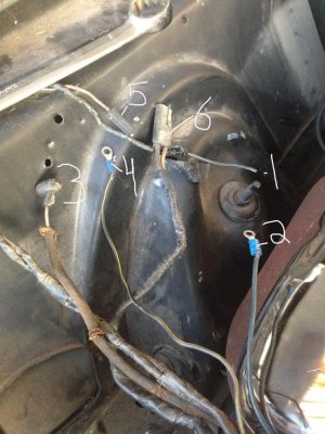
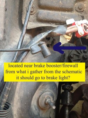
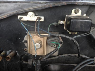
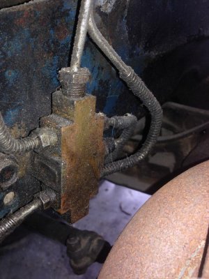
Ok the fire wall plug goes to the proportioning valve for the brakes. On the other portion the wiring looks like it has been converted to electronic ignition. #3 is the water temp sender. #6 looks like an electronic ignition distributor plug. I believe #5 is washer motor. The others are a guess but I'll bet #2 is coil Negative. #4 is coil positive. and #1 is alternator field plug. Check here for the factory stuff.
http://www.mymopar.com/index.php?pid=27
And here for the ignition
https://www.google.com/webhp?source...2&ie=UTF-8#q=mopar electronic ignition wiring
Doug
http://www.mymopar.com/index.php?pid=27
And here for the ignition
https://www.google.com/webhp?source...2&ie=UTF-8#q=mopar electronic ignition wiring
Doug
- Local time
- 1:34 PM
- Joined
- Jan 14, 2009
- Messages
- 2,266
- Reaction score
- 1,895
- Location
- Shoreline, Washington
Appears to be a Mopar electronic ignition conversion;
1. Can’t tell, connector cut off, can’t make out the color code.
2. Coil primary (will need to check polarity, + side should come from ballast resistor)
3. Engine temp sensor
4. Coil primary (will need to check polarity, + side should come from ballast resistor)
5. Windshield washer pump?
6. Distributor pick-up plug
Second picture is the brake pressure differential switch lead, switch is located on the distribution block. Normally mounted to the inner fender, under the master cylinder.
bigmanjbmopar
Newb with a view
Second picture by brakes looks like the brake warning light wire goes to the switch built into the valve. 1st pic hard to tell color of wires but #2 dark green would be horn relay with #4 to horn relay. #5 looks like it would go to the washer pump connector based on its location or horn itself, #3 looks like it goes to the Alternator term. #6 looks like a lighting connector. is #1 black with a trace? original connectors off of #2 & #4 obviously are long gone so hard to say, #2 is a thicker gauge wire so it could be part of the alt. according to the diagram.
Just study the diagram real good and trace them back through the harness to the fire wall or under dash, a lot of it will make sense if you do. A lot of times it takes this to ID the wires as the starting location will tell you what end device it goes to. sometimes things change color in route.
Hard to say what is what here is the wiring diagram for you. can you see the colors on each cable?
http://www.mymopar.com/downloads/1968/68BelvedereGTXSatelliteRoadRunnerB.JPG
1968RRTEXAS
Well-Known Member
Thank you for all the responses, hope this may help
1-Black w/white stripe
2-Dark blue
3-purple/pink
4-Black w/yellow stripe
5-Dark Brown
6-Dark Brown and White with brown stripe
*I have a dark green connected to the Alternator field and black wire for ground on Alternator
*The horn isn't connected, so one of those should be for the horn
*I don't have a reservoir or reservoir pump, so I know I will have some leftover
*The coil negative is hooked to the wire off the distributor, nothing hooked to positive (because I don't know what hooks to it)
Pic of the firewall connections
You guys were spot on with the proportioning valve, thanks
1-Black w/white stripe
2-Dark blue
3-purple/pink
4-Black w/yellow stripe
5-Dark Brown
6-Dark Brown and White with brown stripe
*I have a dark green connected to the Alternator field and black wire for ground on Alternator
*The horn isn't connected, so one of those should be for the horn
*I don't have a reservoir or reservoir pump, so I know I will have some leftover
*The coil negative is hooked to the wire off the distributor, nothing hooked to positive (because I don't know what hooks to it)
Pic of the firewall connections

You guys were spot on with the proportioning valve, thanks

dvw
Well-Known Member
If #1 is blk/white it should be the horn, couldn't tell the color in the 1st post. The blk/yellow is electronic ignition. I believe my call outs for #2-#6 are correct. Use the diagrams in the earlier post as your ignition system is not factory 68 but 72 and up. An ohmeter will tell for sure.
Doug
Doug
- Local time
- 1:34 PM
- Joined
- Jan 14, 2009
- Messages
- 2,266
- Reaction score
- 1,895
- Location
- Shoreline, Washington
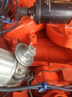
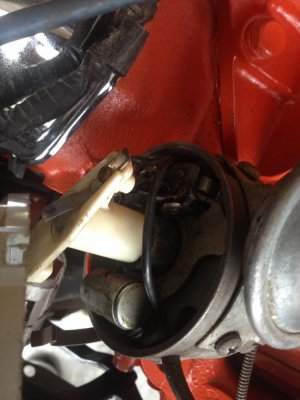
In a MP electronic conversion there isn’t a direct distributor to coil connection, conversion may have been reversed. Post a picture of the distributor leads or what’s under the cap.The coil negative is hooked to the wire off the distributor, nothing hooked to positive (because I don't know what hooks to it)
1968RRTEXAS
Well-Known Member
- Local time
- 1:34 PM
- Joined
- Jan 14, 2009
- Messages
- 2,266
- Reaction score
- 1,895
- Location
- Shoreline, Washington
If it’s not obvious, that’s not a distributor for a Mopar electronic ignition conversion. To use that distributor, the single lead from the distributor connects to the negative side of the coil and one of the pictured ring terminated wires is likely the positive side of the coil. To identify, either power up ign. run and check for something less than battery voltage or ohm it out to one of the ballast resistor terminals, opposite ign. 1 on the ballast resistor.
1968RRTEXAS
Well-Known Member
If it’s not obvious, that’s not a distributor for a Mopar electronic ignition conversion. To use that distributor, the single lead from the distributor connects to the negative side of the coil and one of the pictured ring terminated wires is likely the positive side of the coil. To identify, either power up ign. run and check for something less than battery voltage or ohm it out to one of the ballast resistor terminals, opposite ign. 1 on the ballast resistor.
It wasn't obvious, thank you. So now I have to decide to upgrade my distributor or get rid of the Box and harness off the firewall. What is your opinion? Advantage and disadvantage if you don't mind
- Local time
- 1:34 PM
- Joined
- Jan 14, 2009
- Messages
- 2,266
- Reaction score
- 1,895
- Location
- Shoreline, Washington
My opinion? Replace the distributor with an electronic version, have been running them since way back when. Never had a problem.
Similar threads
- Replies
- 8
- Views
- 291
- Replies
- 9
- Views
- 1K
- Replies
- 1
- Views
- 520

