• When you click on links to various merchants on this site and make a purchase, this can result in this site earning a commission. Affiliate programs and affiliations include, but are not limited to, the eBay Partner Network.

Ignition Wiring

Landon

Active Member
Local time
2:23 AM
Joined
Feb 23, 2016
Messages
31
Reaction score
2
Location
Houston
1969 Coronet. Does anyone have a clear answer on how to wire in my MSD6A? I have the car running and driving, but just feel like there is a better way of doing it. I have my coil connected to the MSD box, and the MSD box heavy red & black fed from the battery correctly.

The small red from the distributor & the small red from the MSD box are supposed to both be tied into 12v ignition per MSD diagram, but I had to tie them into the line side of the voltage regulator with the brown (start) wire and the dark blue (run) wire. Is this correct? Should all 3 be connected to the line side of the voltage regulator? I do not have any wires going to my 2 pole ballast resistor...
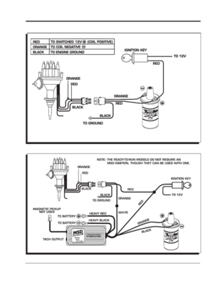
msd.png
 
The small red from the distributor & the small red from the MSD box are supposed to both be tied into 12v ignition per MSD diagram, but I had to tie them into the line side of the voltage regulator with the brown (start) wire and the dark blue (run) wire.

I assume you mean the ballast resistor which has a brown (start) and dark blue (run) wire.
The alternator "should" have Dark blue and Dark blue w/ tracer attached as per drawing.
If you are using the ballast resistor wires (brown & dark blue) tied together you can use them as a ignition switch source.
The power source will change over to the other wire as the key is cycled through the start and run position but does not matter.

upload_2020-7-22_19-39-5.png
 
I assume you mean the ballast resistor which has a brown (start) and dark blue (run) wire.
The alternator "should" have Dark blue and Dark blue w/ tracer attached as per drawing.
If you are using the ballast resistor wires (brown & dark blue) tied together you can use them as a ignition switch source.
The power source will change over to the other wire as the key is cycled through the start and run position but does not matter.

View attachment 978290

I am not running a ballast resistor. The brown "start" wire that used to feed the resistor is now tied to the voltage regulator, along with the dark blue. These 2 wires, along with the 2 red from my distributor and msd box, are tied together at the voltage regulator. Is this ok?

As for the alternator is has the heavy black feeding the battery through the ammeter, a green field wire from other side of voltage regulator, and a violet wire connected to horn relay per the diagram.
 
I am not running a ballast resistor. The brown "start" wire that used to feed the resistor is now tied to the voltage regulator, along with the dark blue. These 2 wires, along with the 2 red from my distributor and msd box, are tied together at the voltage regulator. Is this ok?
Ah ok, that is actually the same as i described so it should work well.

As for the alternator is has the heavy black feeding the battery through the ammeter, a green field wire from other side of voltage regulator, and a violet wire connected to horn relay per the diagram.
Yes, sorry i actually was talking about the alternator regulator. :)

Up to you how you want to do it, but here is how i hooked up my MSD Blaster SS coil voltage supply. (Using it with a MSD Ready To Run distributor)
I tied the brown (start) and Dark blue (run) wires together, and they energize a relay.
That relay feeds the MSD coil with 12Volt directly from the battery through a heavy wire during start and run position.
You could, as you have the MSD6A, hook up the 2 red wires to that relay as well in that case so they all are controlled by 1 relay.

But that is just optional, the way you hooked it up now also works. :thumbsup:
 
It sounds like you're on track but I'm confused that you have the wire from the distributor going to 12V switched power? The distributor wire connects to the white wire coming from the MSD box (if you're running points).
And yes the small red wire from the MSD box goes to 12V switched power wherever you choose to get that power.
 
Last edited:
Ah ok, that is actually the same as i described so it should work well.


Yes, sorry i actually was talking about the alternator regulator. :)

Up to you how you want to do it, but here is how i hooked up my MSD Blaster SS coil voltage supply. (Using it with a MSD Ready To Run distributor)
I tied the brown (start) and Dark blue (run) wires together, and they energize a relay.
That relay feeds the MSD coil with 12Volt directly from the battery through a heavy wire during start and run position.
You could, as you have the MSD6A, hook up the 2 red wires to that relay as well in that case so they all are controlled by 1 relay.

But that is just optional, the way you hooked it up now also works. :thumbsup:
if your brown (start) and blue (run) wires both go to said relay, what is feeding your voltage regulator??
 
It sounds like you're on track but I'm confused that you have the wire from the distributor going to 12V switched power? The distributor wire connects to the white wire coming from the MSD box (if you're running points).
And yes the small red wire from the MSD box goes to 12V switched power wherever you choose to get that power.
the orange wire from the dist. is fed from the white wire from the MSD box. The dist. and the box each have a small red wire that needs 12v ignition source...
 
if your brown (start) and blue (run) wires both go to said relay, what is feeding your voltage regulator??

The wires to the ballast resistor i am using.
I use a alternator with internal voltage regulator.
 
The wires to the ballast resistor i am using.
I use a alternator with internal voltage regulator.
nice. I wish I would have bought an alt. with an internal regulator
 
Auto Transport Service
Back
Top