You are using an out of date browser. It may not display this or other websites correctly.
You should upgrade or use an alternative browser.
You should upgrade or use an alternative browser.
Front Wheel Bearing Seal
- Thread starter Chargered
- Start date
65wgn440
Well-Known Member
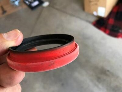
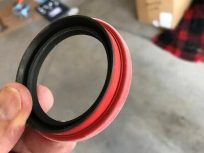
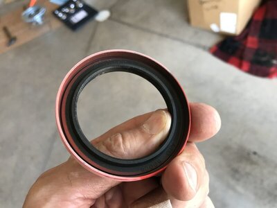
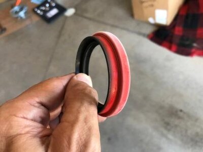
Smaller diameter section should face out from bearing.Can double check by looking for tension spring on lip seal, spring will always go towards protected side (bearing).
- Local time
- 8:24 PM
- Joined
- Jan 29, 2018
- Messages
- 20,942
- Reaction score
- 64,552
- Location
- Midland Ontario, Canada
Rubber lip (smaller diameter side) out..


Last edited:
Chargered
Well-Known Member
I don't see the spring on either side of this seal. I got the bearings and seals from Dr. Diff. These are going on the larger diameter bearing rotors from the 73 and up mopars. When you say the smaller diam section, are you talking about the inner part of the seal where there are two lips one with a slightly smaller diam and one with a slightly larger diam, not the big long lip I'm hanging onto in the pics?Smaller diameter section should face out from bearing.Can double check by looking for tension spring on lip seal, spring will always go towards protected side (bearing).
pdiz
Well-Known Member
Page 22-7, Wheels-Bearings-Tires, of the 1973 Dodge and Plymouth (I have both) Factory Service Manual, tends to agree with everyone else has said with a very vague diagram. To clarify, the first, second, and fourth pictures, the area where your thumb is, that's what everyone is saying should hang out of the disc brake rotor and touch the spindle (or the little white foam gasket on the spindle, if you have that). But if you actually read page 22-8, and ignore the vague diagram, it says the seal goes INWARD, and that seems to be backed by TheRamManInc's youtube channel, "Rotor Grease Seal Installation":
()
This is how I installed them because I didn't even think to double check the shop manual. And doing it this way required me to hammer the outer race of the inner wheel bearing (hope that makes sense) all the way down until it hit a machined lip within the rotor. After all was said and done, everything fit beautifully, there's no rubber gasket rubbing against the spindle at all times, etc., and this seems to be further backed up by another one of his videos "Mopar Disc Spindle Assembly - By TheRamManInc.com":
I mean look how beautiful it sits on the spindle! He seems to be an old-school mechanic and knows his stuff, but at the same time, it looks like he has the outer wheel bearing on backwards, but I think he just messed up when he propped it all together for the video.
But now I'm starting to doubt everything in the world because of the vague picture in the shop manual...
I guess one way to help answer all of this is, do you only hammer the outer race of the inner wheel bearing flush with the rotor hub, or do you bring it down as far as it can go until it hits the lip within the rotor? If you only hammer it until it is flush with the rotor hub, I can see why people think the rubber seal goes outward, because it fits nicely in the hub assembly as well.
Last edited:
Chargered
Well-Known Member
Page 22-7, Wheels-Bearings-Tires, of the 1973 Dodge and Plymouth (I have both) Factory Service Manual, tends to agree with everyone else has said with a very vague diagram. To clarify, the first, second, and fourth pictures, the area where your thumb is, that's what everyone is saying should hang out of the disc brake rotor and touch the spindle (or the little white foam gasket on the spindle, if you have that). But if you actually read page 22-8, and ignore the vague diagram, it says the seal goes INWARD, and that seems to be backed by TheRamManInc's youtube channel, "Rotor Grease Seal Installation":
()
This is how I installed them because I didn't even think to double check the shop manual. And doing it this way required me to hammer the outer race of the inner wheel bearing (hope that makes sense) all the way down until it hit a machined lip within the rotor. After all was said and done, everything fit beautifully, there's no rubber gasket rubbing against the spindle at all times, etc., and this seems to be further backed up by another one of his videos "Mopar Disc Spindle Assembly - By TheRamManInc.com":
I mean look how beautiful it sits on the spindle! He seems to be an old-school mechanic and knows his stuff, but at the same time, it looks like he has the outer wheel bearing on backwards, but I think he just messed up when he propped it all together for the video.
But now I'm starting to doubt everything in the world because of the vague picture in the shop manual...
I guess one way to help answer all of this is, do you only hammer the outer race of the inner wheel bearing flush with the rotor hub, or do you bring it down as far as it can go until it hits the lip within the rotor? If you only hammer it until it is flush with the rotor hub, I can see why people think the rubber seal goes outward, because it fits nicely in the hub assembly as well.
View attachment 995208
View attachment 995209
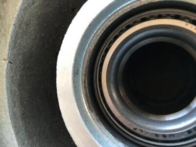
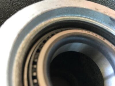
I drove the inner bearing's outer race all the way down as far as it would go. When you do that the seal lip fits perfectly inside of the hub and extends down to touch the outer rim of the bearing. But everyone seems to indicate it goes the other way pointing out of the rotor which is also they way your diagram shows. The SM for my 70 Charger also says the lip goes inward, but not sure if they mean inward in the rotor or inward towards the car? I'll be damned if I know which is correct, but I guess I'll follow everyone's advice here and what your diagram shows.
Chargered
Well-Known Member
Page 22-7, Wheels-Bearings-Tires, of the 1973 Dodge and Plymouth (I have both) Factory Service Manual, tends to agree with everyone else has said with a very vague diagram. To clarify, the first, second, and fourth pictures, the area where your thumb is, that's what everyone is saying should hang out of the disc brake rotor and touch the spindle (or the little white foam gasket on the spindle, if you have that). But if you actually read page 22-8, and ignore the vague diagram, it says the seal goes INWARD, and that seems to be backed by TheRamManInc's youtube channel, "Rotor Grease Seal Installation":
()
This is how I installed them because I didn't even think to double check the shop manual. And doing it this way required me to hammer the outer race of the inner wheel bearing (hope that makes sense) all the way down until it hit a machined lip within the rotor. After all was said and done, everything fit beautifully, there's no rubber gasket rubbing against the spindle at all times, etc., and this seems to be further backed up by another one of his videos "Mopar Disc Spindle Assembly - By TheRamManInc.com":
I mean look how beautiful it sits on the spindle! He seems to be an old-school mechanic and knows his stuff, but at the same time, it looks like he has the outer wheel bearing on backwards, but I think he just messed up when he propped it all together for the video.
But now I'm starting to doubt everything in the world because of the vague picture in the shop manual...
I guess one way to help answer all of this is, do you only hammer the outer race of the inner wheel bearing flush with the rotor hub, or do you bring it down as far as it can go until it hits the lip within the rotor? If you only hammer it until it is flush with the rotor hub, I can see why people think the rubber seal goes outward, because it fits nicely in the hub assembly as well.
View attachment 995208
View attachment 995209
By the way, thank you very much for posting the videos and the SM directions. That was very helpful. Thanks!
- Local time
- 7:24 PM
- Joined
- Oct 18, 2008
- Messages
- 3,411
- Reaction score
- 3,031
- Location
- Kindersley,Saskatchewan, Canada
Yes the bearing race gets installed all the way into the hub. Then the bearing. Then the seal goes in with larger diameter next. Post #10 shows the proper way. Kim
Last edited:
Chargered
Well-Known Member
Thanks for the feedback, but damn, now I'm really confused because I have people telling me both ways.Yes the bearing race gets installed all the way into the hub. Then the seal goes in with larger diameter next. Kim

- Local time
- 8:24 PM
- Joined
- Jan 29, 2018
- Messages
- 20,942
- Reaction score
- 64,552
- Location
- Midland Ontario, Canada
I haven't seen anyone here tell you to put it in the other way. Here's one installed in my drum hub the same way...

Chargered
Well-Known Member
Kim said, "Yes the bearing race gets installed all the way into the hub. Then the seal goes in with larger diameter next. Kim". I think he is saying the lip goes in first. Also, this seems to be what pdiz was saying.I haven't seen anyone here tell you to put it in the other way. Here's one installed in my drum hub the same way...
View attachment 995351
It looks like your hub is different, the bearing sits up higher in the hub. On those 73 and later disc brake rotors with the larger diameter bearing, the bearing sits down further in the hub about a 1/4 inch below where the seal seats against a shoulder in the hub. So there is about a 1/4 drop from where the seal seats to the bearing which makes it look like the seal is designed to have the lip extend down from the shoulder to the bearing. You can see the shoulder in this pic, and the darker area is the 1/4" drop to the bearing, the lip seems to fit perfectly here. Plus the SMs say the lip goes inward.
You could be right, I'm just pointing out that this rotor design is different from the drum design in your pic. Right now, on one rotor I have it installed the way you describe with the lip going outward.
- Local time
- 8:24 PM
- Joined
- Jan 29, 2018
- Messages
- 20,942
- Reaction score
- 64,552
- Location
- Midland Ontario, Canada
It's not what either of them are saying... look at pdiz's 22-7 drawing even.. it shows the smaller diameter lip pointing OUT of the hub. Did you not see the picture of the rotor I posted yesterday!!?? I only posted a drum hub shot to show you they all go that way, it's a dust skirt that rides in a recess of the spindle.
- Local time
- 7:24 PM
- Joined
- Oct 18, 2008
- Messages
- 3,411
- Reaction score
- 3,031
- Location
- Kindersley,Saskatchewan, Canada
Fit the seal onto the spindle first. It’s not rocket science. I guess u have to decide which half of the ppl to believe. Lol. Kim
Chargered
Well-Known Member
Thanks for all the help here folks. Cass over at Dr. Diff also confirmed it goes outward. This is why I like this forum, you guys are always helpful.
pdiz
Well-Known Member
Wait a sec now, just for the record, I'm Team Innie. I just caught that OP (aka "Chargered") stated he's using the "larger diameter bearing rotors," so I'm going to go out on a limb here and guess that he's running the 11.75" 1976-up B-Body/1979-up R-Body unicast, ribbed, and reinforced "cop car" rotors (A2/A17/5121 bearings/races/seals), soooo... Let's hold our horses here because now the 1973 FSM may not be relevant any more and can be tossed out of the equation altogether.
For example, the diagram shows a METAL lip, but OP has a rubber lip (not a big deal, I know parts can change throughout the years), but then says to install the lip inward (I would think into the rotor). It also says to install the inner wheel bearing flush with the rotor, yet these 11.75" rotors require one driving that puppy down until it hits the inner lip of the rotor which is actually recessed, not flush. Due to all these inconsistencies, I'm going to say it's a result of misinterpretation, replacement parts changing from how the originals looked, and the mixing and matching of parts from the 11.75" brake upgrade.
Let me try to find a 1976+ B-Body or equivalent manual that shows those 11.75" rotors and I will come back with my results.
Also, not related to anything, but do people ACTUALLY fill up the entire "wheel hub grease cavity" with grease per the shop manual? I can't imagine just dumping an entire can of wheel bearing grease in there, but, I will if I'm supposed to!
Last edited:
- Local time
- 8:24 PM
- Joined
- Jan 29, 2018
- Messages
- 20,942
- Reaction score
- 64,552
- Location
- Midland Ontario, Canada
So you're are going to jam the metal/rubber, smaller diameter, dust skirt INTO the bearing. Good luck with that and yes I fill the cavity just shy of clearing the spindle with grease and have for over 40 years. Others just pack the bearings and seem to have success with that.
pdiz
Well-Known Member
So you're are going to jam the metal/rubber, smaller diameter, dust skirt INTO the bearing. Good luck with that and yes I fill the cavity just shy of clearing the spindle with grease and have for over 40 years. Others just pack the bearings and seem to have success with that.
Nope. As stated before, the 11.75" rotors have their outer wheel bearings recessed further in than others, and when installed, the dust skirt perfectly butts up against the wheel bearing up/race. I did it this way, and the FSM text seems to back it up, and so do the youtube videos. I'm not saying I did it the proper way, but until there is evidence that I'm completely wrong, I'll live with it.
Also, thanks for the information about packing the grease into the spindle. I've had Mopars for 34 years and never did this, but I am going to from now on. What did you use, a grease gun and a wheel-bearing grease cartridge, or just gloop it in there with a spoon? lol
- Local time
- 8:24 PM
- Joined
- Jan 29, 2018
- Messages
- 20,942
- Reaction score
- 64,552
- Location
- Midland Ontario, Canada
Popsicle stick... 


pdiz
Well-Known Member
OMG, I about died when you wrote "popsicle stick." This is the exact reason why I don't throw anything away because I always find a use for it.
Okay, fair enough. For some reason, I thought you actually had to FILL the entire cavity, not just coat the edges, but then now that I think about it, all the grease would just get pushed out by the spindle when you go to install it! lol
Ranger16
Well-Known Member
I have always just packed the bearings. What's the reason for filling the cavity? I remember reading that in the FSM, but the reasoning eludes me.I fill the cavity just shy of clearing the spindle with grease and have for over 40 years. Others just pack the bearings and seem to have success with that.
Similar threads
- Replies
- 1
- Views
- 537
- Replies
- 5
- Views
- 940
- Replies
- 15
- Views
- 925
- Replies
- 6
- Views
- 1K

