• When you click on links to various merchants on this site and make a purchase, this can result in this site earning a commission. Affiliate programs and affiliations include, but are not limited to, the eBay Partner Network.

Oscilloscope - no idea how to use it !

That’s quite a coincidence, I was just looking for a scope to check the coils on my pos ford motorhome V10.
Hard to justify the cost for a tool I might not use again
 
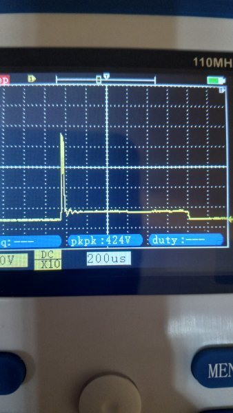
So I'm up 400 volts then negative 300v ? How is that possible ? Should it not hit 0 volts and stop?
The coil generates a magnetic field which builds when energised, then collapses when the power is removed (switched vis points typically).

Imagine bouncing someone on a blanket - when they come down, they typically go below the horizontal plane of the people holding the blanket....ready for the next bounce upwards. Same effect as the voltage peaking and troughing.
 
That’s quite a coincidence, I was just looking for a scope to check the coils on my pos ford motorhome V10.
Hard to justify the cost for a tool I might not use again

This one was only $35CAD. It's only a single channel and handheld . But hey seems like it might be ok for the random checks and diagnostic i plan to use it for!

I'm on a search for a amp clamp at a decent price. Those seem to be little harder to find
 
I have a love hate relationship with picoscope. My favorite is my old Tektronix THS730A. That was before Tektronix got bought and went under the same ownership as Fluke. Tektronix then gave the hand held scope market to Fluke and just focused on the high end scope market. I don't much care for the Fluke scopes but they do work.

I use a PicoScope 4425. The software is free to download if you just want to play around with their guided tests for some basic training.

Their website has a lot of information on how to use a scope and what your base settings should be for certain applications.

PicoScope automotive lab scopes and diagnostic equipment
I taught automotive at a technical college for many years. The Pico scope was the quickest for the students to learn with. I have used ignition scopes since the late 70's I still use one today and many times on my dyno when an engine doesn't run right a scope quickly diagnoses if the issue is in the ignition system. While you can use the grid to observe exact voltages I have used one so much that just looking at the image as a picture usually tells me what I need to know. Keeping a wave form library is a must if you want to get the most out of your scope. And a Pico is super easy to save waveforms on your computer. Lots of website to view wave forms. But the best way is to just check sensors that you know are good, save the image and then compare to sensors you think may be defective. And for example, MSD ignitions have a different wave form due to the way they work, and you will find very few of those images in online wave form libraries. IATN is a good site with a large waveform library. One thing I do is hook a scope to the fuse that feed the electric fuel pump, very easy to see the condition of high mileage fuel pumps and replace before they leave you beside the road. And another super neat way to use a scope is with a vacuum transducer you can tell a bunch about the valve train of an engine with one. You can use an amp's probe to do a relative compression test to find weak cylinders without taking a spark plug out.
 
Playing with this again today. What I can't seem to get or "see" is any sort of dwell or charging of the coil ?

The coil should charge and hopefully saturate , and possibly see a limiting signal before the switch opens and the high voltage spike to fire the plug.

Any idea what I'm doing wrong ?
 
Can you continue to keep the trigger and change the timebase to zoom in on this section of the waveform? That is probably the coil charge portion?

photo.png
 
If you look at this paper you should be able to capture what is described on page one:

Point A: is the instant at which the contact points open thus causing the magnetic field to collapse through the coil’s primary winding. A very high voltage is thus generated in the secondary winding and this continues to rise — until a spark jumps across the distributor rotor gap and the spark plug gap (point B). The voltage at which this occurs is known as the ‘ionization’ or the ‘firing’ voltage and may be anywhere between 5 kV and 1 5 kV depending on the factors outlined above.

1752883468788.png


chrome-extension://efaidnbmnnnibpcajpcglclefindmkaj/https://commons.princeton.edu/58-ti...loads/sites/75/2018/08/ignition_waveforms.pdf
 
I did try that , I can take a picture of it tomorrow .

But when i change the time base, that spike turns into very fine wave pattern. Similar to what you see at the end of the orginal full wage length.

There is a slope up and then spike. Followed by very tight wave .

I will get picture of it tomorrow . Will make kore sense hahaa
 
If you look at this paper you should be able to capture what is described on page one:

Point A: is the instant at which the contact points open thus causing the magnetic field to collapse through the coil’s primary winding. A very high voltage is thus generated in the secondary winding and this continues to rise — until a spark jumps across the distributor rotor gap and the spark plug gap (point B). The voltage at which this occurs is known as the ‘ionization’ or the ‘firing’ voltage and may be anywhere between 5 kV and 1 5 kV depending on the factors outlined above.

View attachment 1887124

chrome-extension://efaidnbmnnnibpcajpcglclefindmkaj/https://commons.princeton.edu/58-ti...loads/sites/75/2018/08/ignition_waveforms.pdf


It is that E to F I am looking for .. where switch close and I should see a drop in voltage before the coil start to charge?
 
It is that E to F I am looking for .. where switch close and I should see a drop in voltage before the coil start to charge?
I believe A to B is the large spike you captured on the scope.
 
You can use an inductive pick-up from a timing light to see the spark going to the plug.

With a scope you can only measure voltage. If you measure voltage across a resistor then you are measuring current.

Keep working on the trigger part - that feature will overlap all the spark firing lines. If something is inconsistent it should stick out.

When measuring voltage at the coil (primary and secondary), you'll see the spikes and oscillations.

*** Never measure the secondary side of the coil with a scope. It will generate 20,000+ volts and fry your scope!
 
So I picked up a cheap little oscilloscope to play around with.

I was hoping to get some reading from my ignitio coil , to try and compare with 2 different setups. Also I belive they can be useful for checking alternators among other things.

Basically just another tool I thought would be neat have and learn to use.

That's where the problem comes in! I don't really know how to use this thing ! I watched a few you tube video but they seem a bit vague and I'm not quite grasping some of it.

Here is my first wave form I got off my coil hooked up to the negative side.

The time frames and voltage scales all determine what you see on the screen and accuracy of the readings ?

People that know how to use these will be able to tell if I have my settings correct from my pics.

Just looking for some input. View attachment 1883830View attachment 1883832
A scope can be the best diagnostic tool...
It shows signal strength, voltage, current, for audio stuff even hum levels.
That (1) reason why for audio products Marantz brand actually built a scope into their top AM/FM
tuners and receivers..

Just my $0.02...
 
Auto Transport Service
Back
Top