• When you click on links to various merchants on this site and make a purchase, this can result in this site earning a commission. Affiliate programs and affiliations include, but are not limited to, the eBay Partner Network.

1970 Plymouth Air Grabber Info questions

moparmarks

I'm just a guy with a screwdriver.
FBBO Gold Member
Local time
8:48 AM
Joined
Jul 31, 2011
Messages
8,951
Reaction score
4,083
Location
Western Colorado High Desert
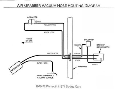
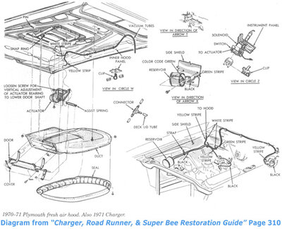
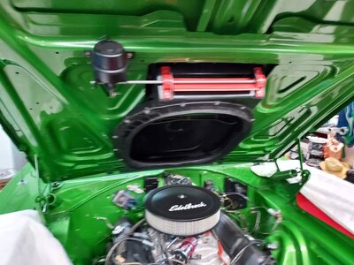
Looking for pictures of hose routing including firewall, vacuum reservoir and location, and switch mounting for a 1970 Plymouth GTX. Getting all kinds of incorrect pics on Google.
Many thanks.
 
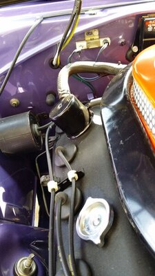
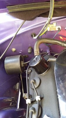
I can get u a pic of mine in my 70 gtx
 
here is some diagrams I used for a 1970 GTX I sold this years

6586898-AirGrabberhoseschematic (1).jpg 6588595-FAD7071Bbodyairgrabber.jpg
 
You will want to identify what plant your car is from....there are differences in hose routings & firewall holes between plants.
 
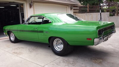
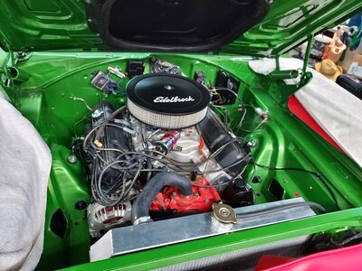
It is a St Louis car that has an N-96 hood added but has nothing else. It is a GTX but was cut decades ago and has been a drag car ever since so not real concerned about being totally correct but would like it to be close. I don't know where to go through the fire wall, where the reservoir is mounted and what not.

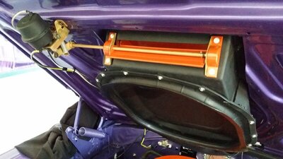
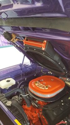
20210625_105940.jpg 20211102_101926.jpg 20211102_101928.jpg
 
There are dimples in your firewall for the vacuum can mounting as well as the hose routing. You can see from photos above the can mounting location. if you have the can you should be able to match it up to the 2 holes required. I believe the phot above is correct for hose routing through firewall for SL plant. I will look tomorrow through my archived photos to see what I have.
 
Auto Transport Service
Back
Top