Hi,
I had a request for more information on moving the headlight relays to the engine bay. I did not have time to draw up a "better" schematic, but here is a link to my existing one.
Legend:
1. H/L on: headlights on signal from headlight switch.
2. CL: close limit switch line.
3. MO: motor open field line
4. MC: motor close field line
5. CAB: top half, refers to parts inside the car.
6. The little light: "Lamps not locked" light
7. HOSW: "hold open switch"
8. FW: refers to the firewall bulkhead connector and firewall side of the engine bay/headlight wiring harness junction by the battery.
9. HL: refers to the headlight side of the engine bay/headlight wiring harness junction by the battery.
Here's how it works (DISCONNECT YOUR BATTERY BEFORE PROCEEDING. DO THIS AT YOUR OWN RISK IF YOU DO NOT UNDERSTAND ELECTRICAL SYSTEMS):
1. Leave the control relay in the car alone.
2. Add two jumpers in the car to bypass the open and close relays:
a. Close relay: red SOLENOID to black SOLENOID (there are two red lines! The heavy one with a white tracer feeds the motor close fields. You want the red one that comes from the control relay output!)
b. Open relay: jumper light green (headlights "on" signal from the headlight switch) to the violet (motor open fields) connector.
3. In 2a, this bypasses the close relay and sends the "close" signal from the control relay to the "hold open" switch. The signal from the hold open switch (black) goes through the firewall to the headlight harness connector I'll discuss in a minute. Beware of this jumper- if you do things wrong, it will place a dead short of 12V through the 30A breaker in the kickpanel out to the close limit switch. It is good to test this circuit without relays, then add them in the engine bay
4. In 2b, this bypasses the open relay and sends the "open" signal through the firewall on the "motor open" line that normally powers the motors. If you do this wrong, you will send power to a motor field on a line not designed to support that current!
5. You now have the following at the bulkhead connector:
a. A "close" signal on the CL line with the HOSW inline.
b. An "open" signal on the MO line.
c. The OL line remains in place.
d. The MC line is disconnected
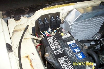
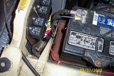
6. I spliced all the relay stuff in between the engine bay/headlight harness connection using pigtails from my old harnesses. If you don't have those, you'll have to figure out what to do on your own from here. It looks like this:
==engine harness==factory connector=>|<=old headlight harness connector==relay and splice==old engine harness connector=>|<==headlight connector==
7. Using the two pigtails, be sure to connect together the park and turn signal lights. Also connect the high and low beams unless you are also adding relays to control those.
8. Add a 30A breaker or inline fuse from the battery. Connect it to the +12V side of both new open and close relays.
9. Connect the switched side of one relay to the MO line (violet) going to the headlight connector. Connect the other relay's swithc output to the MC line (red with tracer) going to the headlight connector
10. Connect the two OL lines (dark green) to the negative side of the solenoid in the open relay. This is necessary to get the "lamps not locked light" working.
11. Connect the MO line (violet) from the firewall to positive side of the open relay. This completes the "open" circuit.
12. Connect the CL line from the headlight side of the harness to the negative side of the close relay solenoid.
13. Conenct the CL line from the firewall to the positive side of the open relay solenoid.
14. Terminate the MC line (red w/tracer) coming from the firewall. It is not used. This completes the "close" circuit.
There you go. I've done my best to make this clear. It's best to test the wiring without relays (use a test light to see the open and close signals turn on and off). Make sure there are no dead shorts where there shouldn't be. Shoot, even jumper straight off the battery and open and close your headlights a bit to make sure you have the right lines for that. If you have your open and close signals working, leave them disconnected, connect the relays, and then jumper the battery to the positive solenoid side of either relay and make sure the relays do their job that way too. Incremental testing is key.
When you're done, you will have relieved your firewall of sourcing 25A (twice), and given your motors the best voltage possible. If you do this, it's also a good time to add relays for your high and low beams. Same principle applies- use the signals to activate relays, feed the relays straight off the battery, send the relay output to the lights in place of the original signals. Your firewall is now 10-20A lighter, again.
Questions are welcome.